Arjun Main Battle Tank (MBT)

The Last Stand

New Member
Joined
Apr 14, 2013
Messages
1,406
Likes
980
Country flag
from crazy arguments like gunner being behind gun mantlet, to main gun configuration, all the way back to where you mistook an arjun for a tank-ex... this is not about being thorough, it's about you grasping for straws.
I was searching for those words :rage:

You found them first.
 

ersakthivel

Brilliance
New Member
Joined
Mar 6, 2011
Messages
7,029
Likes
8,764
Country flag
lol, anything i might be the slightest bit wrong about you latch onto like a tick because i've so consistently destroyed every argument you've laid out:

from crazy arguments like gunner being behind gun mantlet, to main gun configuration, all the way back to where you mistook an arjun for a tank-ex... this is not about being thorough, it's about you grasping for straws.
You destroyed !!!!!!!!!, I hardly noticed,

You are still using your LEO template and plotting Arjun dimensions selectively to vainly argue the points put forth by a few foreign fake tank experts in an utterly useless effort.

Whenever I nail one of your big mistakes You present a stony silence and hop on to some other area and continue to post as if nothing happened.
Remember your bizarre claim that one wrist thickness is 90 mm and a straightened shoe of Ajai shukla standing on Arjun will measure 450 mm if straightened to justify your wrong argument that Arjun turret width measures only around 2950 odd mm across at it's center point.


If you mark the dimensions properly you will only get the same LOS of 800 mm behind the main sight.
 
Last edited:

ersakthivel

Brilliance
New Member
Joined
Mar 6, 2011
Messages
7,029
Likes
8,764
Country flag
lol, anything i might be the slightest bit wrong about you latch onto like a tick because i've so consistently destroyed every argument you've laid out:

from crazy arguments like gunner being behind gun mantlet, to main gun configuration, all the way back to where you mistook an arjun for a tank-ex... this is not about being thorough, it's about you grasping for straws.


[/IMG]

http://s1296.photobucket.com/user/ersakthivel/media/sakthi_zps3683e564.png.html?filters[user]=133772280&filters[recent]=1&sort=1&o=0

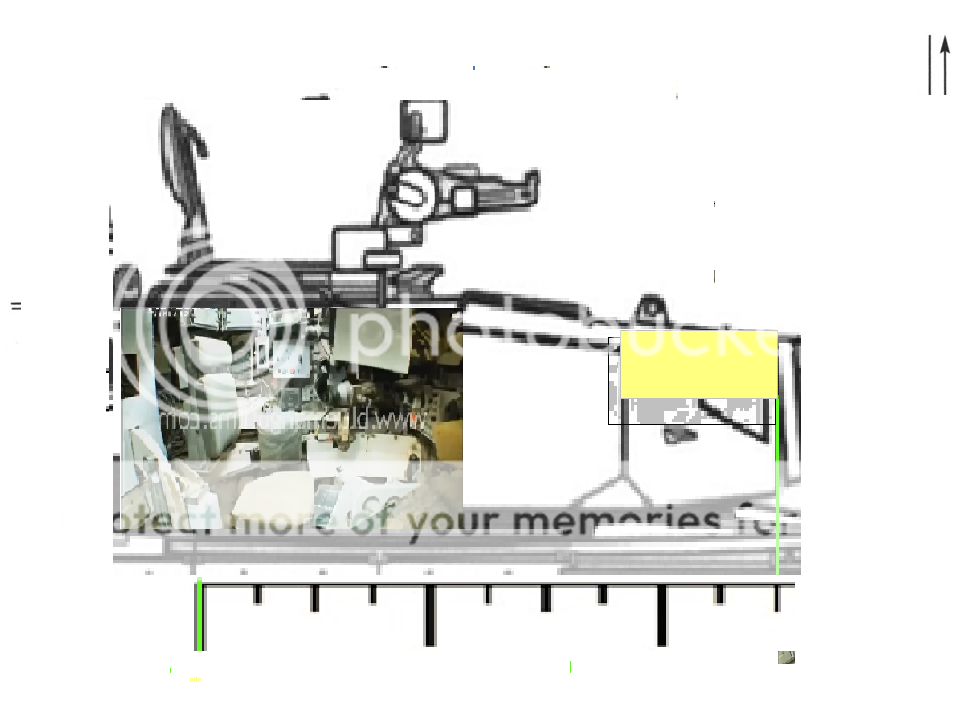
The above drawing is a much better representation of Arjun turret and it shows the LOS behind the main sight clearly.

The yellow rectangle is the main sight cutaway measuring 700 mm on scale. And the distance between the end of the inlaid photo and the back edge of the main sight cutaway is the armor thickness behind main sight.
Note the vision blocks above the Tc's head in the in laid photo clearly matches the edge of the crew hole in the line drawing with scale and dimensions.
 
Last edited:

ersakthivel

Brilliance
New Member
Joined
Mar 6, 2011
Messages
7,029
Likes
8,764
Country flag


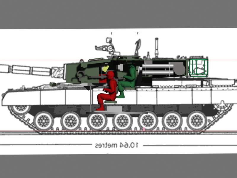
Another comical effort. Look at the head of the Tc in the photos the TC's head is more than 200 mm below the vision block.

But with a view of showing a bigger crew compartment that it actually is you have magnified the size of the TC and the gunner.


Remember this image posted by you, in the following page,

http://defenceforumindia.com/forum/defence-strategic-issues/44522-arjun-vs-t90-mbt-68.html

It exposes all your mistake in the 3D model. Just add another 300 mm to reach the back edge of the gunner's main sight block and you know LOS behind the main sight is close to 800 mm as I claimed.
 
Last edited:

ersakthivel

Brilliance
New Member
Joined
Mar 6, 2011
Messages
7,029
Likes
8,764
Country flag


Another comical effort. Look at the head of the Tc in the photos the TC's head is more than 200 mm below the vision block.

But with a view of showing a bigger crew compartment that it actually is you have magnified the size of the TC and the gunner.


Remember this image posted by you, in the following page,

http://defenceforumindia.com/forum/defence-strategic-issues/44522-arjun-vs-t90-mbt-68.html

What is the space (length in mm) occupied by the head of the man?

200 mm at the most.The head occupies 3 cm space on the screen.

The total length of the full red line from the back of the chair to red box (vision blocker I suppose )measured by scale on the screen is exactly 15 cms.

SO 15/3=5X200 mm=1000 mm is the actual length is my guess.Am I right?
It exposes all your mistake in the 3D model. Just add another 300 mm to reach the back edge of the gunner's main sight block and you know LOS behind the main sight is close to 800 mm as I claimed.

You once claimed that this distance is 700 mm. Now claiming it to be more than 1000 mm.
 

ersakthivel

Brilliance
New Member
Joined
Mar 6, 2011
Messages
7,029
Likes
8,764
Country flag


In fact the gunner's seat back rest is clearly behind the big white display as per the photo above. But in your model the big white display is more than 400 mm infront of the big white display.

Correct that and bring them in vertical line and you will get a true picture.

There is no way Tc 's foot is going to scratch the back of the gunner as per your model. SO you have to scale down the TC and gunner size as well.


The driver seat is clearly visible from the photo above crew hatch , where is it in your 3D model?

Considering the lower height of gunner's seat most of his knee space room will go above the gunner's head according to the photo. But you have purposely marked his knees bending behind the back of the gunner's seat in an effort to enlarge the crew compartment and show a lesser LOS behind the main sight,


From this photo below the gunner's seat back rest is inline with the edge of the crew hatch hole at 2000 mm distance behind the gun mantle plate front tip,
Because the gun end point is visible in both the photos which marks the position of the gunner's seat back rest .

LOOK there is no room for the TC to place his foot below the gunner's seat back rest as shown in your model above.

And his knees are over the head of the gunner as per the photos above not behind the gunner's seat back rest.

As per these photos the gunner's head is directly below the big white display ,

Because both the gun end point and the white display in front of the Tc are visible on a same vertical line at a point more than

2000 mm distance behind the gun mantle plate front tip, you are cleverly misrepresenting the whole arrangement to suit your needs.

but in your model gunner's head is more than 300 mm in front of the big white display.


but in your photo it is far ahead of the 2000 mm mark.


Look at the total height of the crew compartment it is 2 meters only as per the scale in the line drawing.

But in your model the gunner alone measures more than 1.5 meter in seated position , So you must down scale the crew men size as well.

Does an average indian male measures 1.5 meters in seated position? A bit lower is my opinion.
 
Last edited:

ersakthivel

Brilliance
New Member
Joined
Mar 6, 2011
Messages
7,029
Likes
8,764
Country flag

http://s1296.photobucket.com/user/ersakthivel/media/sakthi_zps3683e564.png.html?sort=3&o=0

The above drawing in the link above is a much better representation of Arjun turret and it shows the LOS behind the main sight clearly.

The yellow rectangle is the main sight cutaway measuring 700 mm on scale. And the distance between the end of the inlaid photo and the back edge of the main sight cutaway is the armor thickness behind main sight. It is around 800 mm approx.

Note the vision blocks above the Tc's head in the in laid photo clearly matches the edge of the crew hole in the line drawing with scale and dimensions.

For some reason that drawing is not properly uploading here. If some one can copy it and upload it please do it. Thanks.
 
Last edited:

ersakthivel

Brilliance
New Member
Joined
Mar 6, 2011
Messages
7,029
Likes
8,764
Country flag


The drawing below is a much better representation of Arjun turret and it shows the LOS behind the main sight clearly.

The yellow rectangle is the main sight cutaway measuring 700 mm on scale. And the distance between the end of the inlaid photo and the back edge of the main sight cutaway is the armor thickness behind main sight. It is around 800 mm approx.

Note the vision blocks above the Tc's head in the in laid photo clearly matches the edge of the crew hole in the line drawing with scale and dimensions.


The rough draw may not be upto scale, it is a rough and ready alteration of what militarista posted to communicate my point of view.

1. A ----------the distance between gun mantlet plate front tip and the back edge of the main sight cutaway= 700mm according to your previous posts.

2. B ----------- The distance between the back edge of the main sight cutaway and the opening for roof top vision block inside Arjun turret (the back edge of the main gunner's sight block is in vertical line with roof top vision block opening inside Arjun turret) = 800 mm(LOS for composite armor)


3. C ---------- the distance between the back edge of the main gunner's sight block and the gunner's seat back head rest=500 mm.

4. D ------------the distance between the gunner's seat back head rest and the vertical standing crew hatch cover in the line drawing posted below = 500mm. gunner's seat back head rest is in vertical straight line with the front arc edge of the round crew hole.

So A + B + C + D = 700 + 800 + 500 + 500 = 2500 mm.


1.The red rectangle marked measurement A starts at the gun mantlet plate tip and ends at the main sight cutaway back side edge.

2. The blue rectangle signifying B starts at the where A ends and stops at back edge of the gunner's main sight bloc back edge.


3. The yellow rectangle C starts at the point where B ends and stops at the back side of the gunner's seat headrest's back edge.


4.The green rectangle D starts at where C ends and stops at the swivel or the base of the vertical standing crew hatch cover base in the only line drawing dimensions posted in this post above.


1. the length of A-------The red rectangle's length is 700 mm.

2.The length of B-------The red rectangle's length is 800 mm.

3.The length of C-------The red rectangle's length is 500 mm.

4.The length of D-------The red rectangle's length is 500 mm.

A + B + C + D =2500 mm.


The end of the green rectangle D is exactly at 2500 mm from the front tip of the gun mantle plate according to the drawing with dimensions from where you supposedly took you measurements for your 3D model.

The following photo validates my measurement of the length of the green (D) and yellow(C) rectangle.


1.The Tc seat edge the ending point of the yellow rectangle is situated at 2500 mm behind the gun mantle plate tip according to the line drawing with scale measurements.

2.The gunner's seat , the ending point of the yellow rectangle is locate at at 2000 mm from gun mantle plate tip according to the line drawing with scale measurements.

3.Since the Tc himself has just 500 mm seat breadth the gunner too will have the same 500 mm. So the ending point of the blue rectangle is at 1500 mm from gun mantle plate tip according to the line drawing with scale measurements.


And the photo above is a clear proof that the roof top vision block brings light into the Arjun turret in a slanting rectangular channel at the point of the end of the blue rectangle i.e a point in vertical line with the back side of the gunner's main vision block with binocular like eye pieces.

4.Also since the main sight cutaway stops at 700 mm from the gun mantle plate tip ,

according to the line drawing with scale measurements the ending point of the red rectangle , is locates at 700 from the gun mantle plate tip according to the line drawing with scale measurements.


So 1500 mm- 700 mm =800 mm is the LOS armor thickness behind the main sight without any doubt.

And the roof top vision block brings light to the gunner's main vision block through a slating rectangular channel.

If the main sight is pushed up like the latest model LEOs the Arjun can have 300 mm more LOS behind the main sight than any LEO model, because it's turret is longer and lower than LEO.

So any 380 mm LOS or 300 mm LOS behind the main sight is pointless according to the photo proofs
So all the four consistent continuous measurement marking arrow lines will give you undeniable evidence of very strong protection behind Arjun main sight back side contrary to your views based on faulty 3 D model is my opinion based on the line drawing and the photographs in this page,

But I have never seen the Arjun tank . So I don't claim it is the concrete truth from my first hand experience of arjun. but the measurement leaves no doubt , especially Arjun turret is not only shorter and wider , but longer than Leo- 2 as well. it is this small crucial detail you omit.
 
Last edited:

ersakthivel

Brilliance
New Member
Joined
Mar 6, 2011
Messages
7,029
Likes
8,764
Country flag
@ersakthivel

The BR image isn't official according to Kunal Biswas
he referred to the gun photos and the arrangement of FCS as shown in India today . You are totally quoting him out of context.

please give the link to the page when he made that comment and every one will else will know that on what topic he made the comment.
 
Last edited by a moderator:

The Last Stand

New Member
Joined
Apr 14, 2013
Messages
1,406
Likes
980
Country flag
he referred to the gun photos and the arrangement of FCS as shown in India today . You are totally quoting him out of context.

please give the link to the page when he made that comment and every one will else will know that on what topic he made the comment.
Page 346 of this thread.

And he meant it for the Bharat Rakshak image.

And he said that the images taken by India Today are official and from DRDO museum room.

Who is quoting him out of context? Not me.
 

ersakthivel

Brilliance
New Member
Joined
Mar 6, 2011
Messages
7,029
Likes
8,764
Country flag
Page 346 of this thread.

And he meant it for the Bharat Rakshak image.

And he said that the images taken by India Today are official and from DRDO museum room.

Who is quoting him out of context? Not me.


It was this image he meant as coming from museum AFAIK.

because he has not yet commented that the line drawing with dimensions posted by P. Maitra doesn't belong to that of Tank ex or Arjun.
 

ersakthivel

Brilliance
New Member
Joined
Mar 6, 2011
Messages
7,029
Likes
8,764
Country flag
i see you've aligned the vision blocks like a pro:

In my drawing the vision block occupies around 500 mm approx on the scale below.

How much do you expect them to occupy or how much will it affect the overall LOS behind the main sight say it occupies about 600 mm.

If not please re arrange it and show your 380 mm LOS behind the main sight.

Why don't you realign it and prove your drawing expertise rather than trying to fool around with dimensions of human butt in inches in your 3 D modelling?

Is that the way you take measurement in steel beast?
 
Last edited:

The Last Stand

New Member
Joined
Apr 14, 2013
Messages
1,406
Likes
980
Country flag


It was this image he meant as coming from museum AFAIK.

because he has not yet commented that the line drawing with dimensions posted by P. Maitra doesn't belong to that of Tank ex or Arjun.
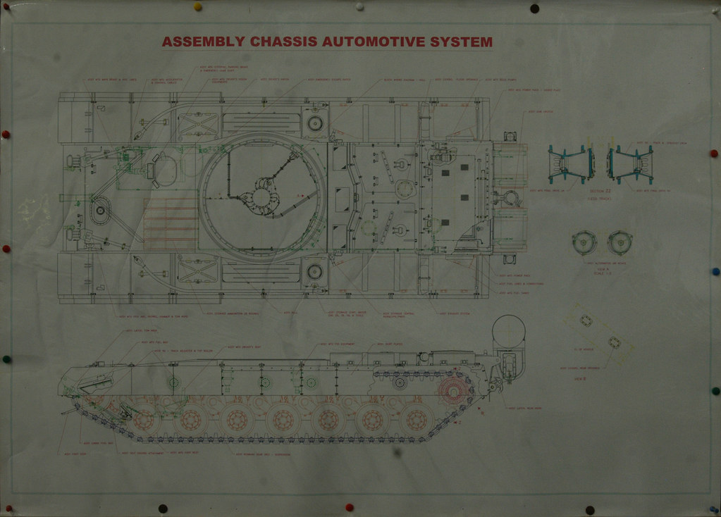
That's what I meant too. That image was supposed to have come in India Today. (The Chassis Automotive system)

The Line drawing? Let's forget that for a while and wait for newer images and DefExpo 2014
 

Dejawolf

New Member
Joined
Dec 22, 2012
Messages
579
Likes
241
In my drawing the vision block occupies around 500 mm approx on the scale below.

How much do you expect them to occupy or how much will it affect the overall LOS behind the main sight say it occupies about 600 mm.
i expect them to align with the vision blocks in the drawing. that's how much space i expect them to occupy.

If not please re arrange it and show your 380 mm LOS behind the main sight.

Why don't you realign it and prove your drawing expertise rather than trying to fool around with dimensions of human butt in inches in your 3 D modelling?

Is that the way you take measurement in steel beast?
i've already proven my drawing expertise and wasted enough time making pictures for you, how about you get busy in paint and realign those vision blocks properly with the line drawing,
 

ersakthivel

Brilliance
New Member
Joined
Mar 6, 2011
Messages
7,029
Likes
8,764
Country flag
That's what I meant too. That image was supposed to have come in India Today. (The Chassis Automotive system)

The Line drawing? Let's forget that for a while and wait for newer images and DefExpo 2014
Since you are not going to let go of it, I am giving you a simple,exercise that will help you know whether the line drawing or correct or not?

Because you got to find it out yourself, No one is going to release a new line drawing in def expo-2014.

Go to wiki , or any official DRDO sight , or google and try to get dimensions of the height , width , length of the Arjun tank.

Also go to google images and type images for Arjun MBT

.You will get tons of pictures. You down load one of them.There are many scales in the line drawing below. Cut one and paste it on a paint soft ware.


Then import the side view of Arjun with hatch cover standing vertically and fit it on the scale.

And check it with official dimensions you got from any official site.

Then post your findings here. I too haven't done that yet. But considering the credibility of BR I have no reason to doubt it either.

SO do the work and post the finding here. Got it.

Looking forward to your first post with photo and scale on it.

If you are not able to do it. Please don't blame it on your short term memory loss.

Thanks.
 
Last edited:

ersakthivel

Brilliance
New Member
Joined
Mar 6, 2011
Messages
7,029
Likes
8,764
Country flag
i expect them to align with the vision blocks in the drawing. that's how much space i expect them to occupy.


i've already proven my drawing expertise and wasted enough time making pictures for you, how about you get busy in paint and realign those vision blocks properly with the line drawing,


Take a good look at the position of the driver's seat back in the model you posted above. It is 300 mm in front of the crew hatch front edge.

Take a good look at the photo below.Where is the driver's seat back rest?

It is close 100 mm behind the front edge of the crew hatch hole edge above Tc. Such an elementary mistake can not be covered up by calling my post as junk.


If you still have any doubt lok at the picture below. In this pic the driver seat back rest is not visile. But the gun breech sledge's back edge is clearly visible.

In th photo above the gun breech sledge's edge is in horizontal straight line with the driver seat back rest.

So according to this pic also it is correctly proved that the top of the driver's seat back rest is within the crew hole ,i.e just 100 mm behind the front edge of the Tc's crew hatch hole.


SO these pictures prove that you are consistently posting a patently wrong 3 D model to buttress your false debating point of just 380 mm LOS behind main sight. Need I say more?

Just move the gunner back by 300 mm. And you will get 380 + 300 =680 mm min LOS behind main sight even as per your faulty 3D model.
 
Last edited:

Articles

Top