Arjun Main Battle Tank (MBT) Mark II

Kunal Biswas

Member of the Year 2011
Ambassador
Joined
May 26, 2010
Messages
31,122
Likes
41,041
Arjun mantlet is bigger it is possible that some portion of Gunner position is covered ..

I cannot say for sure, Until there are photo evidence here which will be only during 2014 ..

there's no tank in the world where a crew member can sit behind the gun mantlet.
the gunner sits behind the main sight, as he does in every other tank ever made.
 

ersakthivel

Brilliance
Senior Member
Joined
Mar 6, 2011
Messages
7,029
Likes
8,763
Country flag
Arjun mantlet is bigger it is possible that some portion of Gunner position is covered ..

I cannot say for sure, Until there are photo evidence here which will be only during 2014 ..
See the first of the three pictures,

Where is the end point of the main sight cut away and where is the end point of the gunner's seat?

Gunner seat edge is located almost behind the middle point of the main sight cut away,

The edges of the main sight cutaway and the edges of the Tc's seat are not in line as dejawolf insists them to be in his drawings.


A large portion of the gunner's seat is right behind the gap between the gun covering plate and the cutaway for the main sight, which is heavily armored

about half the gunner seat is behind the big gun covering plate on the turret front.

Only half the gunner's seat is behind the main sight cut away.

And if the orange vision block in front of the gunner is located at the middle of the gunner's seat, (because main sight instruments have their eye piece at one of their corners) there should be some offset between the position of the gunner's seat and Tc.


So this seating arrangement in the picture which places the center point of the gunner's seat right behind the center point of the main sight cutaway is clearly wrong based on the photo above,

 
Last edited:

Dejawolf

Regular Member
Joined
Dec 22, 2012
Messages
579
Likes
241
Cannot say may be @sayareakd sir know, It was showed in defexpo once ..

Not different, They are same but more compact as it was placed on T-72 Chassis..
don't see why it would have to be more compact to be fitted to a T-72 chassis, center hull is about the same width on both tanks.
only reason for the larger total width of the arjun, is because of wider tracks, and thicker sideskirts.
 
Last edited by a moderator:

Dejawolf

Regular Member
Joined
Dec 22, 2012
Messages
579
Likes
241
So this seating arrangement in the picture which places the center point of the gunner's seat right behind the center point of the main sight cutaway is clearly wrong based on the photo above,
another nonsensical statement by Ershaktivel. nothing new from those fronts as usual.


green line indicates center point of gunners seat.
how about you check your "facts" before going on a long tirade about things.
 

sayareakd

Mod
Joined
Feb 17, 2009
Messages
17,734
Likes
18,952
Country flag
Cannot say may be @sayareakd sir know, It was showed in defexpo once ..

Not different, They are same but more compact as it was placed on T-72 Chassis..
sir only seen Arjun from Inside, No one was present on Tank Ex, just got close look at its skirt and taken few pics.
 
Last edited by a moderator:

ersakthivel

Brilliance
Senior Member
Joined
Mar 6, 2011
Messages
7,029
Likes
8,763
Country flag
another nonsensical statement by Ershaktivel. nothing new from those fronts as usual.


green line indicates center point of gunners seat.
how about you check your "facts" before going on a long tirade about things.
So you have shifted your name calling from ARJUN MBT thread to here, Welcome
 

ersakthivel

Brilliance
Senior Member
Joined
Mar 6, 2011
Messages
7,029
Likes
8,763
Country flag
the obvious arrangement for anyone who has spent more than 5 seconds inside of a tank:

I asked you to mark the three dimensions A, B, C , not draw four arrow marks in different colors.

Look carefully at the BR scale drawing below, the pivot base of the hatch cover is right below the vertical standing crew hatch

cover,it this point that is 2500 mm behind the turret front tip

Why is it way behind the vertical standing crew hatch cover in your drawing above

Do you even have the faintest idea how a pivot operates in a real world?

If you want the hatch cover to stand vertically at 90 degrees the pivot base must be right below the hath cover , not behind the hatch cover. it is a simple real world fact, just open the door of your room and stop it at 90 degrees ,

where is the pivot keel?

it is right in line with the door.


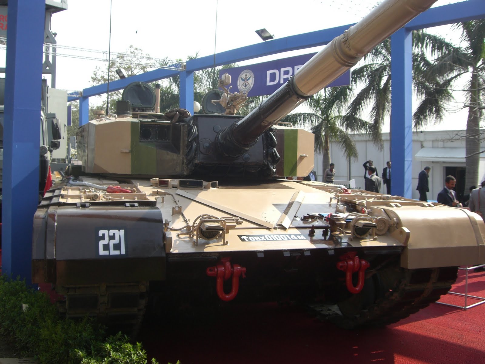
I hope you will identify the turret below belongs to Arjun,

Where is the pivot base and the vertical standing crew hatch cover ?

On the same vertical line or 250 mm apart,?


In case you don't know the A, B, C, D of Arjun , See below,

The drawing below is a much better representation of Arjun turret and it shows the LOS behind the main sight clearly.

The yellow rectangle is the main sight cutaway measuring 700 mm on scale. And the distance between the end of the inlaid photo and the back edge of the main sight cutaway is the armor thickness behind main sight. It is around 800 mm approx.

Note the vision blocks above the Tc's head in the in laid photo clearly matches the edge of the crew hole in the line drawing with scale and dimensions.


The rough draw may not be upto scale, it is a rough and ready alteration of what militarista posted to communicate my point of view.

1. A ----------the distance between gun mantlet plate front tip and the back edge of the main sight cutaway= 700mm according to your previous posts.

2. B ----------- The distance between the back edge of the main sight cutaway and the opening for roof top vision block inside Arjun turret (the back edge of the main gunner's sight block is in vertical line with roof top vision block opening inside Arjun turret) = 600 mm(LOS for composite armor)


3. C ---------- the distance between the back edge of the main gunner's sight block and the gunner's seat back head rest=600 mm.

4. D ------------the distance between the gunner's seat back head rest and the vertical standing crew hatch cover in the line drawing posted below = 600mm. gunner's seat back head rest is in vertical straight line with the front arc edge of the round crew hole.

So A + B + C + D = 700 + 600 + 600 + 600 = 2500 mm.


1.The red rectangle marked measurement A starts at the gun mantlet plate tip and ends at the main sight cutaway back side edge.

2. The blue rectangle signifying B starts at the where A ends and stops at back edge of the gunner's main sight bloc back edge.


3. The yellow rectangle C starts at the point where B ends and stops at the back side of the gunner's seat headrest's back edge.


4.The green rectangle D starts at where C ends and stops at the swivel or the base of the vertical standing crew hatch cover base in the only line drawing dimensions posted in this post above.


1. the length of A-------The red rectangle's length is 700 mm.

2.The length of B-------The red rectangle's length is 600 mm.

3.The length of C-------The red rectangle's length is 600 mm.

4.The length of D-------The red rectangle's length is 600 mm.

A + B + C + D =2500 mm.


The end of the green rectangle D is exactly at 2500 mm from the front tip of the gun mantle plate according to the drawing with dimensions from where you supposedly took you measurements for your 3D model.

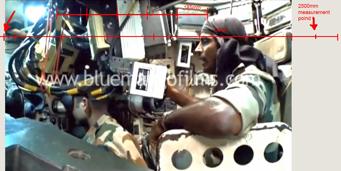
The following photo validates my measurement of the length of the green (D) and yellow(C) rectangle.


1.The Tc seat edge the ending point of the yellow rectangle is situated at 2500 mm behind the gun mantle plate tip according to the line drawing with scale measurements.

2.The gunner's seat , the ending point of the yellow rectangle is locate at at 2000 mm from gun mantle plate tip according to the line drawing with scale measurements.

3.Since the Tc himself has just 600 mm seat breadth the gunner too will have the same 600 mm. So the ending point of the blue rectangle is at 1500 mm from gun mantle plate tip according to the line drawing with scale measurements.


And the photo above is a clear proof that the roof top vision block brings light into the Arjun turret in a slanting rectangular channel at the point of the end of the blue rectangle i.e a point in vertical line with the back side of the gunner's main vision block with binocular like eye pieces.

4.Also since the main sight cutaway stops at 700 mm from the gun mantle plate tip ,

according to the line drawing with scale measurements the ending point of the red rectangle , is locates at 700 from the gun mantle plate tip according to the line drawing with scale measurements.


So 1300 mm- 700 mm =600 mm is the LOS armor thickness behind the main sight without any doubt.

And the roof top vision block brings light to the gunner's main vision block through a slating rectangular channel.

If the main sight is pushed up like the latest model LEOs the Arjun can have 300 mm more LOS behind the main sight than any LEO model, because it's turret is longer and lower than LEO.

So any 380 mm LOS or 300 mm LOS behind the main sight is pointless according to the photo proofs
So all the four consistent continuous measurement marking arrow lines will give you undeniable evidence of very strong protection behind Arjun main sight back side contrary to your views based on faulty 3 D model is my opinion based on the line drawing and the photographs in this page,

But I have never seen the Arjun tank . So I don't claim it is the concrete truth from my first hand experience of arjun. but the measurement leaves no doubt , especially Arjun turret is not only shorter and wider , but longer than Leo- 2 as well. it is this small crucial detail you omit.


So even as per the above photo of yours the distance C+D=1200 mm only.
 
Last edited:

ersakthivel

Brilliance
Senior Member
Joined
Mar 6, 2011
Messages
7,029
Likes
8,763
Country flag
we can clearly see the Tc seat head rest right below base pivot of the vertical crew hatch cover


There can not be a 250 mm horizontal distance between them.
 

ersakthivel

Brilliance
Senior Member
Joined
Mar 6, 2011
Messages
7,029
Likes
8,763
Country flag
LOL, why not, it demonstrates beautifully how insane your claims about 800mm behind sight is.

here it is again:

You are still marking the basic 2500 mm point wrongly,

look below,

turret front gun covering plate tip is at 2 meters , and the base pivot is at 4500 mm.

So i am right in saying that the base pivot of the hatch vertical standing cover is 2500 mm behind the front tip of turret,

And you are wrong in disputing this point again and again in a meaningless way,


Mark the four consecutive dimensions A, B, C, D totaling 2500 mm like in the picture below,

with arrow marks or different color rectangular blocks and you will know how wrong you are.Why are you avoiding it?

 
Last edited:

Dejawolf

Regular Member
Joined
Dec 22, 2012
Messages
579
Likes
241
You are still marking the basic 2500 mm point wrongly,

look below,

turret front gun covering plate tip is at 2 meters , and the base pivot is at 4500 mm.

the 2500mm measure was never taken from the front of the gunshield, it was taken from the front of the turret, which you conveniently ignored, so that your insane needs for armour that can stop thermonuclear warheads can be appeased. no tank NEEDS 1000mm RHAe front turret armour.
 

Dejawolf

Regular Member
Joined
Dec 22, 2012
Messages
579
Likes
241
You are still marking the basic 2500 mm point wrongly,

look below,

turret front gun covering plate tip is at 2 meters , and the base pivot is at 4500 mm.

So i am right in saying that the base pivot of the hatch vertical standing cover is 2500 mm behind the front tip of turret,

And you are wrong in disputing this point again and again in a meaningless way,


Mark the four consecutive dimensions A, B, C, D totaling 2500 mm like in the picture below,

with arrow marks or different color rectangular blocks and you will know how wrong you are.Why are you avoiding it?

i dont have to mark them, they can be clearly seen.
 

ersakthivel

Brilliance
Senior Member
Joined
Mar 6, 2011
Messages
7,029
Likes
8,763
Country flag
i dont have to mark them, they can be clearly seen.
MARK IT.

You are making fancy 3d models , So it is not a huge problem , I suppose,

A discussion on a drawing without dimension is purely subjective and not objective , fundamentally worth less waste of time,

Without dimensions no technical drawing is complete.
 

ersakthivel

Brilliance
Senior Member
Joined
Mar 6, 2011
Messages
7,029
Likes
8,763
Country flag
the 2500mm measure was never taken from the front of the gunshield, it was taken from the front of the turret, which you conveniently ignored, so that your insane needs for armour that can stop thermonuclear warheads can be appeased. no tank NEEDS 1000mm RHAe front turret armour.
Who told you that?

you once claimed that the side view of your 3d model was based on BR scaled line drawing with dimensions as below ,


It is in that drawing the tip of the turret front(including the gun covering plate) is 2500 mm behind the pivot base of the hatch cover,

It is from that datum point we should take all the dimensions if you want to refer any point along the length of the turret. That is the basic rule of technical drawing. you can not just say i will exclude the covering plate,

Even if you exclude the covering plate the 2500 mm will become 2400 mm and and all other dimensions will shrink proportionally and you will still get the 600 to 800 mm LOS behind main sight,

If you have ny trouble understanding such simple concept please ask any technical drawing guy you know, He will explain with examples,

To clear the confusion you can mark the 4 consecutive dimensions A, B, C, D totaling 2500 mm.

So MARK IT.
 
Last edited:

Dejawolf

Regular Member
Joined
Dec 22, 2012
Messages
579
Likes
241
Who told you that?

you once claimed that the side view of your 3d model was based on BR line drawing with dimensions ,

It is in that drawing the tip of the turret front(including the gun covering plate) is 2500 mm behind the pivot base of the hatch cover,

To clear the confusion you can mark the 4 consecutive dimensions A, B, C, D totaling 2500 mm.

So MARK IT.
nah, i've marked 2500mm already on the picture, you can fill in your ABCD. or are you afraid it will prove to everyone how foolishly wrong you've been?
this image shows how my turret perfectly lines up with the BR line drawings.
 
Last edited:

ersakthivel

Brilliance
Senior Member
Joined
Mar 6, 2011
Messages
7,029
Likes
8,763
Country flag
nah, i've marked 2500mm already on the picture, you can fill in your ABCD
this image shows how my turret perfectly lines up with the BR line drawings.
Mark it your self,

I am really pleasantly surprised that you are placing such a great trust and respect on my dimensional marking abilities,

thank you very much,

But I don't want be dragged on for another hundred pages with you calling ,"you have marked it wrong" as you are doing it now,

So it is your drawing and you can do it yourself.
 

Dejawolf

Regular Member
Joined
Dec 22, 2012
Messages
579
Likes
241
Mark it your self,

I am really pleasantly surprised that you are placing such a great trust and respect on my dimensional marking abilities,

thank you very much,

But I don't want be dragged on for another hundred pages with you calling ,"you have marked it wrong" as you are doing it now,

So it is your drawing and you can do it yourself.
i have zero trust in your ability to mark dimensions, but i suppose the troll must be fed:
yellow and green is 600mm each, blue is 300mm, red is 760mm
 
Last edited:

ersakthivel

Brilliance
Senior Member
Joined
Mar 6, 2011
Messages
7,029
Likes
8,763
Country flag
i have zero trust in your ability to mark dimensions, but i suppose the troll must be fed:
yellow and green is 600mm each,
I asked you to mark the dimensions in number

Write the how many mm occupied by each of your colored blocks in your own words.

Since you have zero trust in my abilities you can do that yourself.
 
Last edited:

Latest Replies

Global Defence

New threads

Articles

Top