That's it... But is there any step been taken forward in this regard too or would we be depended on Russian engines for these? I think its high time that attention to be paid towards developing CM engines too.CM engines aren't designed for re-use as would be required from an aircraft. Completely different design philosophy, metallurgy etc. Somewhat like comparing pre-2006 F1 engines with family wagon engines.

Kaveri Engine
- Thread starter natarajan
- Start date
More options
Who Replied?Kyubi
New Member
- Joined
- Oct 30, 2013
- Messages
- 486
- Likes
- 512
Manik is a turbofan engine for sub sonic cruise missiles developed jointly by DRDO- GTRE and according to Saurav Jha report in Feb if I am correct several heavier variants of Nirbhay are in various stages of development so as with higher thrust Manik variantsThat's it... But is there any step been taken forward in this regard too or would we be depended on Russian engines for these? I think its high time that attention to be paid towards developing CM engines too.
Sent from my XT1068 using Tapatalk
pmaitra
New Member
- Joined
- Mar 10, 2009
- Messages
- 33,262
- Likes
- 19,600
Can you post a picture of Manik?Manik is a turbofan engine for sub sonic cruise missiles developed jointly by DRDO- GTRE and according to Saurav Jha report in Feb if I am correct several heavier variants of Nirbhay are in various stages of development so as with higher thrust Manik variants
Sent from my XT1068 using Tapatalk
Kyubi
New Member
- Joined
- Oct 30, 2013
- Messages
- 486
- Likes
- 512
Can you post a picture of Manik?
Sent from my XT1068 using Tapatalk
Attachments
-
 26.6 KB Views: 89
GTRE developed Manik 425-kgf thrust turbojet at Aero India 2015
a program at very early stage...

http://thumkar.blogspot.jp/2015/10/rci-developing-275-kgf-thrust-cruise.html
a program at very early stage...
http://thumkar.blogspot.jp/2015/10/rci-developing-275-kgf-thrust-cruise.html
Thanks a lot. I didn't knew about this development.Manik is a turbofan engine for sub sonic cruise missiles developed jointly by DRDO- GTRE and according to Saurav Jha report in Feb if I am correct several heavier variants of Nirbhay are in various stages of development so as with higher thrust Manik variants
Sent from my XT1068 using Tapatalk
- Joined
- Mar 6, 2011
- Messages
- 7,029
- Likes
- 8,764
file:///C:/Documents%20and%20Settings/Administrator/My%20Documents/Downloads/6007-15791-1-SM.pdf
1 Introduction One of the principal requirements of military aircraft of the 1990's, which will operate with high performance, energy efficient engines, is to have superior engine performance over a wide range of flight conditions.
In any aircraft gas turbine engine, it is the flight conditions that have a predominant effect on its performance. It is well-known that the pressure and temperature vary considerably with altitude and ambient condition. This affects the temperature and pressure of the air entering the compressor of the gas turbine engine.
Thus, it would not be possible to design any engine for optimum performance at all flight conditions, since a conventional engine with a fixed design point will give optimum performance at that point only and not for the entire flight spectrum.
2. Design Considerations Hitherto, the practice has been to design the engine for optimum performance at a particular operating condition viz., sea level static at international standard atmosphere (iSA), and to select the engine parameters based on this operating condition.
Thus the ISA sea level static (SLS) condition was the design point which corresponded to a compressor inlet total temperature TI of 288°K and inlet total pressure Pa of 1013 millibar (14.7 psia). Consider now the increase of TI and PI due to varying flight ambient conditions as mentioned above.
An increase in P, is generally advantageous to engine performance, whereas an increase in T, causes a deterioration in performance. The correspondence of the design value of T, of 288°K to different conditions of the flight spectrum is shown in Fig. I.
This design value of inlet temperature is fairly well matched to the transonic Mach, numbers at high altitudes of flight and to the low subsonic Mach numbers at low altitudes of flight, and with the value of TI around 28g°K, the compressor operating point is maintained about the same as that at ISA SLS condition (Fig. 2). For compressor inlet temperatures.
TI lower than 288"K, the compressor performance would be better than that at ISA SLS. But when compressor inlet temperature TI is higher than 288"K, the compressor operating point would move away on the operating line from the design point. As a result, the air mass flow parameter W~%/P, and the pressure ratio P,/P1 would be inferior to the corresponding design point values.
The engine performance would thus be inferior to the design intent. It has been recognized that this fact has to be counteracted for high supersonic cruise at high altitude and for high subsonic operation at low altitude (both cases corresponding to high values of TI).
As a matter of fact, the contemporary high pressure ratio engines lose thrust, often rapidly. Under these conditions, this loss of thrust with increase in TI becomes significant in the case of bypass engines, with thrust drop increasing with increase in bypass ratio.
3. Concept
Now, if the engine cycle could be varied so that the engine operates in most of the flight spectrum nearer the design point, then significant improvement in engine performance could be expected. A variable cycle engine would be an ideal solution for this problem.
The thermodynamic cycle of the engine can be changed either by providing variable bypass ratios andlor by energy inputs in the different flow passages of the engine. The thermodynamic cycle of the engine is primarily dependent on the maximum cycle temperature and compressor pressure ratio as well as on component efficiencies, mechanical losses, etc.
In conventional engines that have to operate at off-design conditions, it has been the practice to maintain the maximum cycle temperature constant i.e. turbine entry temperature is constant at the design value. Consider now the case of high inlet temperature TI discussed above.
At constant maximum turbine entry conditions (under high TI) the corrected engine speed N/~K falls with corresponding drop in W ~/T/P,. It would, therefore, appear that there is a scope for restoring the cycle to operate at the design point, thereby recovering the thrust drop.
A comparatively simple and direct approach to the problem could be achieved by increasing maximum cycle temperature at the design (high TI)
condition
1. This increase in maximum cycle temperature under high TI condition is accompanied by increase in mechanical RPM to maintain the corrected RPM thereby keeping air mass flow parameter and pressure ratio same as that at ISA SLS condition.
In other words, the compressor is made to operate such that the operating point under high T, conditions is the same as that at ISA SLS condition; the operating point is aerothermodynamically retained
2. It is interesting to note that this concept of variable cycle achieved by varying the maximum cycle temperature has been recognised in recent days for the design of engines for combat aircraft with particular reference to supersonic cruise at altitude
3. The ratio of the maximum cycle temperature to that at ISA SLS has been referred to as 'throttle ratio' in recent literature. By employing the concept of high throttle ratio design, one can compensate the significant
thrust drop associated with high pressure ratio engines under high T, conditions. This results in a 'flat rated engine'.
The above concept can be applied both for high Ta pressure ratio straight jet engines and to a limited extent to bypass engines. In a conventional engine, with increase in TI under maximum engine operating conditions, the maximum cycle temperature will be essentially constant.
Hence as TI increases, for fixed maximum cycle temperature, the heat energy added will be less, whereas in the case of an engine employing high throttle ratio design, the maximum cycle temperature increases with increase in TI thus tending to maintain the input of energy.
4. GTX Engine Design
The GTX engine was conceived from the basic observation that if the overall pressure ratio can be retained and simultaneously the turbine entry temperature (maximum cycle temperature) is increased above the design point value, then with increase of TI, the available dry thrust can be significantly increased within the allowable aerothermodynamic limits of the components of the gas turbine engine.
Thus GTX 37-14U is a flat rated engine design based on an early and simplified approach to the variable cycle engine high throttle ratio concept with particular reference to the Indian operating requirements of good dry combat performance at low level, high speed t and high ambient condition.
The engine is a twin spool turbojet with a high compressor pressure ratio having a throttle ratio of 1.13. The performance of this engine and a conventional engine of throttle ratio of unity are compared in Figs 3 to 6. These figures show that both the corrected air flow and pressure ratio with forward speed are well below the design values and there is scope to make use of this underused capacity.
The simplest way would be to open the throttle and thereby increase the thrust. The throttle can be opened till the corrected air flow and compressor pressure ratio arerestored to the design values. This then is the background of the GTX concept.
The effect of throttle ratio higher than unity as in the case of the GTX engine is clearly seen from Fig. 7. Selection of throttle ratio is limited by the maximum cycle temperature which the turbine technology can permit. In the case of the GTX engine, the maximum cycle temperature is limited at present to 1450°K so as not to exceed the material limits of the turbine blades.
Certified Gipsy
New Member
- Joined
- Jan 14, 2016
- Messages
- 93
- Likes
- 116
Where can we download this pdf file from?
GTRE sought technical assistance from IIT, Mumbai, Vazir Institute of Technology to overcome the problem of thrust-to-weight ratio of Kaveri, to no avail.People have to come out of Myth that Private companies are the saviors and do the job better. Private companies are not driven by patriotism they are driven by Profits. Why would a Private entity invest 5000-10000 crores rupees in developing an Engine, testing facilities and R&D. Do they see return of the investment + Profits. Even if they have successfully created one in 10 years how are they assured the orders. Even to start one do they have human resources to do it. Leave alone test facilities which can be bought by money.
Private companies are best as manufacturers as they are driven by profits they will streamline manufacturing and scale whenever the need may be.
Like ADA/HAL which are ready to share manufacturing processes to private players for the subsystems, GTRE will work in developing an required Engine and manufacturing the can be delegated.
Take the situation of Kaveri which cannot be used in the Tejas1 or Tejas2 or NTejas, may be the derivatives are being used in Aura & discussions are for KMGT engine. Will these give the return of the investment incurred. If Private entity is in place of GTRE it would filed Bankruptcy long time ago.
warrior monk
New Member
- Joined
- Nov 24, 2014
- Messages
- 650
- Likes
- 1,114
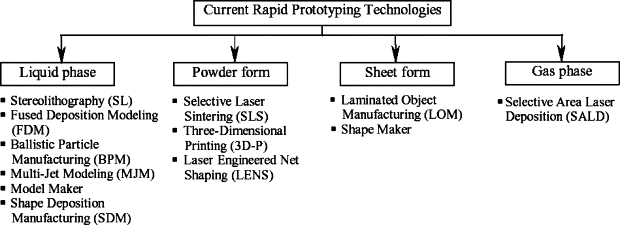
DRDO is using Fused deposition Modeling or FDM for kaveri for rapid prototyping from a CAD file.
According to GTRE
Real Challenge: One of the greatest challenges in designing the Kaveri was positioning its piping runs and line replaceable units (LRUs) on the outside of the aircraft. Many of the LRUs are connected to the interior of the engine with pipes that carry hydraulic fluid, fuel, and lubricants. It was a major challenge to design each piping run to minimize length to reduce weight and cost while avoiding interference.There are approximately 2,500 engine components that had to be included in the assembly.
If GTRE would have considered building the prototype using CNC machining it would have taken a minimum of one year and cost of estimated $60,000 to build the physical prototype assembly another approach GTRE also considered stereolithography, but the project was not well-suited for this prototyping method due to excessive supports needed for components like turbine blades, combustor swirlers, inlet guide vanes and combustors. GTRE also realized that most conventional rapid prototyping methods would have made it necessary to produce solid pipes which would have eliminated the possibility of flow testing.
Best approach- FDM or Fused deposition Modeling. With over 2,500 FDM components, the Kaveri jet engine prototype the most complex rapid-prototype assembly ever created. It took GTRE only 30 days to produce all these components from ABS plastic using two FDM-based Fortus (earlier FDM TITAN) machines. It took another 10 days to assemble the engine. The total cost to produce the FDM assembly was about $20,000.
Courtsey-
IOSR Journal of Mechanical and Civil Engineering (IOSR-JMCE)
e-ISSN: 2278-1684, p-ISSN: 2320-334X
PP 62-68
www.iosrjournals.org
So is the Kaveri engine program on, will we have a LCA prototype flying with Kaveri engine?DRDO is using Fused deposition Modeling or FDM for kaveri for rapid prototyping from a CAD file.
View attachment 7590
According to GTRE
Real Challenge: One of the greatest challenges in designing the Kaveri was positioning its piping runs and line replaceable units (LRUs) on the outside of the aircraft. Many of the LRUs are connected to the interior of the engine with pipes that carry hydraulic fluid, fuel, and lubricants. It was a major challenge to design each piping run to minimize length to reduce weight and cost while avoiding interference.There are approximately 2,500 engine components that had to be included in the assembly.
If GTRE would have considered building the prototype using CNC machining it would have taken a minimum of one year and cost of estimated $60,000 to build the physical prototype assembly another approach GTRE also considered stereolithography, but the project was not well-suited for this prototyping method due to excessive supports needed for components like turbine blades, combustor swirlers, inlet guide vanes and combustors. GTRE also realized that most conventional rapid prototyping methods would have made it necessary to produce solid pipes which would have eliminated the possibility of flow testing.
Best approach- FDM or Fused deposition Modeling. With over 2,500 FDM components, the Kaveri jet engine prototype the most complex rapid-prototype assembly ever created. It took GTRE only 30 days to produce all these components from ABS plastic using two FDM-based Fortus (earlier FDM TITAN) machines. It took another 10 days to assemble the engine. The total cost to produce the FDM assembly was about $20,000.
View attachment 7591
Courtsey-
IOSR Journal of Mechanical and Civil Engineering (IOSR-JMCE)
e-ISSN: 2278-1684, p-ISSN: 2320-334X
PP 62-68
www.iosrjournals.org
- Joined
- Apr 29, 2015
- Messages
- 18,416
- Likes
- 56,946
Don't know that Kaveri or other projects but HAL has successfully tested and 25kN thrust engine. For powering Tejas, we need 35-40. So, we are very near to goal.So is the Kaveri engine program on, will we have a LCA prototype flying with Kaveri engine?
warrior monk
New Member
- Joined
- Nov 24, 2014
- Messages
- 650
- Likes
- 1,114
Why would we give up on our Kaveri program it already has achievedSo is the Kaveri engine program on, will we have a LCA prototype flying with Kaveri engine?
• Air Mass Flow : 78 kg/s
• Bypass Ratio : 0.16
• Pressure Ratio : 21.5
• TET: 1487 K – 1700 K
•Max.Dry Thrust: 52 kN
• Afterburner Thrust: 81 kN
• Thrust / Weight Ratio: 7.8
• Afterburner SFC: 2.03 kg/hr/kg
Need to improve on BLISK , TBC ( Thermal barrier coating) especially under high cyclic condition , improve creep , improve its HP and LP compressor , increase in BPR ( bypass ratio.) , increase in TeT which can happen if there is substantial improvement in metallurgy like 3rd gen Ni based SCB .
No it will not fly on Tejas but with an improved core and metallurgy it might fly on AMCA post 2025. I believe GE may be asked to work with GTRE for the K10 engine.
Anupu
New Member
- Joined
- Dec 22, 2015
- Messages
- 859
- Likes
- 2,866
No we need around 60 Kn of Dry thrust for Tejas Mk II and MK I is getting flak because of it's 48.9 Dry thrust.Don't know that Kaveri or other projects but HAL has successfully tested and 25kN thrust engine. For powering Tejas, we need 35-40. So, we are very near to goal.
Akask kumar
New Member
- Joined
- Jan 28, 2016
- Messages
- 583
- Likes
- 666
nope tejas need around 90 kn.. ....Don't know that Kaveri or other projects but HAL has successfully tested and 25kN thrust engine. For powering Tejas, we need 35-40. So, we are very near to goal.
- Joined
- Apr 29, 2015
- Messages
- 18,416
- Likes
- 56,946
Yep, my mistake.nope tejas need around 90 kn.. ....

R.I.P. 30 character rule.
HariPrasad-1
New Member
- Joined
- Jan 7, 2016
- Messages
- 9,645
- Likes
- 21,138
Yes, 90 kn Wet thrust and 50+ kn dry thrust.nope tejas need around 90 kn.. ....
Kaveri was designed for Tejas with dimensions to fit into the aircraft, now with further weight reduction in MK1A and some tweak in the engine. I think we can put one in Tejas and test. Jags and Mirage have lesser thrust engines so a lesser powered Tejas can be envisaged for a different roles?Why would we give up on our Kaveri program it already has achieved
• Air Mass Flow : 78 kg/s
• Bypass Ratio : 0.16
• Pressure Ratio : 21.5
• TET: 1487 K – 1700 K
•Max.Dry Thrust: 52 kN
• Afterburner Thrust: 81 kN
• Thrust / Weight Ratio: 7.8
• Afterburner SFC: 2.03 kg/hr/kg
Need to improve on BLISK , TBC ( Thermal barrier coating) especially under high cyclic condition , improve creep , improve its HP and LP compressor , increase in BPR ( bypass ratio.) , increase in TeT which can happen if there is substantial improvement in metallurgy like 3rd gen Ni based SCB .
No it will not fly on Tejas but with an improved core and metallurgy it might fly on AMCA post 2025. I believe GE may be asked to work with GTRE for the K10 engine.
HariPrasad-1
New Member
- Joined
- Jan 7, 2016
- Messages
- 9,645
- Likes
- 21,138
Mirage have lesser thrust engines so a lesser powered Tejas can be envisaged for a different roles?
Mirage does nothave a lesser power engine. Jugs have 2 engines.
Articles
-
 India Strikes Back: Operation Snow Leopard - Part 1
- mist_consecutive
- Replies: 9
-
Aftermath Galwan : Who holds the fort ?
- mist_consecutive
- Replies: 33
-
 The Terrible Cost of Presidential Racism(Nixon & Kissinger towards India).
- ezsasa
- Replies: 40
-
Modern BVR Air Combat - Part 2
- mist_consecutive
- Replies: 22
-
Civil & Military Bureaucracy and related discussions
- daya
- Replies: 32