LCA TEJAS MK1 & MK1A: News and Discussion

AbRaj

New Member
Joined
Jan 22, 2016
Messages
1,051
Likes
1,782
Country flag
F-16 Net is most reliable On F-16 Even than Wiki
Porkies Take It like Gospel And All other Military Enthusiast

What Is your Source Of higher TWR of F-16

And What its reliability ????
Are you Porki?
I’m not porki neither is this forum. I will not take that data as face value.
Wiki is ok when baked by link. OEM data sheet will be better.
 

AbRaj

New Member
Joined
Jan 22, 2016
Messages
1,051
Likes
1,782
Country flag
I think you are unaware of the famous paper published on aerodynamic study of Tejas.
Most probably in MWF not in Mk1A. Anyway change will be marginal at best. Even different variants of LCA have different canopy. Just compare them.
:megusta::megusta::megusta:

So you Yourself Don't have Base To Phrase Question

So You are Wasting Are Time For Off-topic flame bating

@hit&run @Indx TechStyle
What Question?
Anyway your bogus forumer is quoting LCA TWR 0.87 which is way lower than official figures.
And Mig 29 have several drawbacks against but TWR isn’t one of them. It has very high twr.
 

WARREN SS

New Member
Joined
Oct 12, 2013
Messages
5,570
Likes
20,878
Country flag
What Question?
Anyway your bogus forumer is quoting LCA TWR 0.87 which is way lower than official figures.
That Is For IOC variant Available in 2015

Mig-29 has different variants
Like F-16has blocks

Many Use Different engines as well That effect TWR
 

AbRaj

New Member
Joined
Jan 22, 2016
Messages
1,051
Likes
1,782
Country flag
That Is For IOC variant Available in 2015

Mig-29 has different variants
Like F-16has blocks

Many Use Different engines as well That effect TWR
We have different engine in FOC?

Just curious to know from where the 1.07 figure came from???
 

WARREN SS

New Member
Joined
Oct 12, 2013
Messages
5,570
Likes
20,878
Country flag
We have different engine in FOC?
They not Stretched To there Limits And Load Combinations You Need Certifications for each


Majority F-16's blocks Got FOC Decade's Ago That Is why its Figures are Available openly For Analysis

LCA Actual performance specs Will Be openly available in next 5-6 years When its Fully operational

And Indicator Will be FOC variant

Example Combat radius And Range Upgraded in FOC
 

HariPrasad-1

New Member
Joined
Jan 7, 2016
Messages
9,645
Likes
21,138
Country flag
@AbRaj

For your information. Go through this article containing extract of that researcher paper which is not available now. Here aerodynamics is discussed in detail. I have removed many images as not more than 8 images are allowed to be posted here. So follow the link for details.

  • Indranil Roy & Nilesh Rane
  • 1 year ago
Tracking The Tejas: The Design Evolution Of An Indian Fighter Part-I

It is no overstatement to say that the Tejas Light Combat Aircraft (LCA) program has made significant progress of late with the Mk1 variant being officially granted Final Operational Clearance (FOC) on February 20, 2019 and its production picking up pace at Hindustan Aeronautics Limited (HAL). Seven of the thirteen Initial Operational Clearance (IOC) standard Tejas Mk1 already in service with No. 45 squadron or the Flying Daggers of the Indian Air Force (IAF) were handed over in the last 11 months alone. The remaining three IOC-standard single-seater aircraft meant for the Flying Daggers are slated to join the squadron by the end of April 2019. The Tejas MK1 is now also a regular at IAF air exercises, raking up high range scores and generally winning the confidence of its users. As such, the focus has now shifted to the development and production of the Tejas Mk1A variant since India’s Defence Acquisition Council has accorded approval for the acquisition of 83 units of the type by the IAF. Before we turn to analyzing developments related to the Mk1A and further evolution of the Tejas platform, it is important to profile the current capabilities of the baseline Mk1 itself.


LCA Tejas Mk1
Tejas Mk1 is a ‘fourth-generation lightweight, single-engine, multi-role, tactical fighter aircraft. It employs an unstable tailless compound delta-wing configuration, optimized primarily for maneuverability and agility’. Over 90 percent of its surface, and over 45 percent of its airframe by weight is made of composite structures. This is one of the highest usage of composites in an aircraft of any kind, anywhere in the world. This extensive use of composites has lowered the aircraft’s weight by 21 percent and reduced its part count by 40 percent, as opposed to what would have been the case had it been of all-metal construction.


The aircraft has intentionally been made longitudinally unstable to enhance maneuverability. In fact, its static margin, i.e. a measure of its instability (and hence maneuverability) is also one of the highest for any modern fighter aircraft [18]. To recover stability and provide good handling qualities, it is equipped with a fully redundant quadruplex digital fly-by-wire flight control system (FCS). This FCS is one of the biggest accomplishments of the LCA program. Its robustness has ensured an accident-free test record of over 4,300 test flights. The aircraft has also been equipped with advanced autopilot capabilities like auto-level (in case of pilot disorientation), safe altitude recovery (which automatically pulls up the aircraft if it comes too close to the ground) and auto navigation modes.


In-service aircraft are certified to fly from -3.5 to +8.0 Gs, up to an altitude of 50,000 feet, a top speed of Mach 1.6, and an angle of attack (AoA) of up to 24 degrees. The test pilots have stretched the prototypes even further, up to 8.5 Gs, and 26 degrees AoA. At the 2016 Bahrain Air Show, the Mk1 had even demonstrated a low speed pass at 110 knots. The FCS has now been updated to lower the minimum speed to 100 knots, at which point auto recovery is initiated. The 2016 demonstration at Bahrain also showcased another important feature: Following the above-mentioned low speed pass the aircraft immediately proceeded to accomplish a vertical climb. The ability to accelerate while in a climb is a virtue that only fighters with a thrust to weight ratio (TWR) of above 1.0 possess. At Bahrain, the Mk1 also showcased an instantaneous turn rate (ITR) of near 30 degrees per second and a sustained turn rate (STR) of between 15 to 16 degrees per second. A minimum radius turn of 350 metres (m) radius was also exhibited. All of these are extremely respectable numbers for air to air (A2A) combat roles.


The Mk1 is equipped with a powerful MultiMode Radar (MMR) which has A2A, air to sea, and air to ground (A2G) target detection modes. In A2A, the Tejas Mk1 is currently capable of firing R-73 close combat missiles (CCMs) and Derby beyond visual range A2A missiles (BVRAAMs). In the future, the Mk1 is likely to be integrated with India’s Astra BVRAAM as well. Together, with state-of-the-art helmet mounted display and sight (HMDS) and hands on throttle-and-stick (HOTAS) controls, and coupled with navigation aides like Very High-Frequency (VHF) Omnidirectional Range (VOR) / Instrument Landing System (ILS) and tactical air navigation system (TACAN), Tejas Mk1 allows the pilot to concentrate on “head-down” mission-critical requirements rather than worry about basic flying.


One of the Tejas’s greatest strengths is its A2G weapon delivery accuracy. In all flight tests and air exercises so far, the Mk1 has consistently garnered some of the highest range scores of all the aircraft in the IAF’s inventory. Not only can it carry 250 kg and 450 kg dumb bombs, but also laser guided bombs (LGBs) which are guided to their targets using a Litening laser designation pod (LDP). A single LGB can be carried on either the center-fuselage, wing-inboard or midboard weapon stations. For dumb bombs, two can be carried in tandem in the wing-inboard pylons, whereas one each can be carried in the center-fuselage and wing-midboard locations.


The Mk1’s all-weather and day/night capability has been proven in various extreme hot and cold weather trials, from Jaisalmer to Leh. For example, in Leh, the aircraft was successfully started after a cold soak of 42 hours where the temperature reached near -20°C . In each of the three attempts, the aircraft started effortlessly even on a partially drained battery. The reader might be reminded that a few Multi-Medium Role Combat Aircraft (MMRCA) contestants had actually failed this test during trials for that tender. Similarly, in hot and high trials, the aircraft took off with 1.9 tons (50 percent) of its max payload, which is an astounding feet given its highly swept delta wings.


The Tejas Mk1 has a total of five ‘wet’ points: one underneath the fuselage and two underneath each wing. The hardpoint underneath the fuselage can carry a 725 litre (L) subsonic drop tank or a 710 L supersonic tank (still under development). The wing inboard pylon can carry a subsonic drop tank of 1200 L while the midboard can carry a drop tank of 800 L. Although the MK-1’s developer, the Aeronautical Development Agency (ADA) publishes a conservative ferry range of 1750 km, ferry flights of ranges of nearly 2100 km have been completed in the past. The FOC version of the Tejas MK-1 has also been fitted with a fixed refueling probe which can be used to refill all of it internal and external fuel tanks, effectively doubling its range and endurance.


Enter the Tejas Mk1A
Now even while ADA was developing the Tejas Mk2 for the IAF, HAL proposed a simpler interim upgrade. Thus emerged the Tejas Mk1A which will be equipped with an ELTA EL/M- 2052 active electronic scanned array (AESA) radar along with a compatible electronic warfare suite, which would include a self protection jammer (SPJ) pod carried on the outboard wing pylon. This position was found to derive maximum performance out of the pod. On the the outboard pylon, two CCMs would be carried on a dual-rack pylon as shown in Figure 1. This configuration was found to have lowest drag penalties among a variety of studied configurations [19].


In addition to the above changes, HAL would upgrade some line replacement units (LRUs) to cater to obsolescence management, weight reduction, ease of manufacture and maintenance. The aircraft would also be fitted with an Onboard Oxygen Generation System (OBOGS) which would allow pilots to undertake long endurance flights. The turnaround time of the aircraft has also been reduced by means of hot refueling, a feature that SAAB wanted to showcase on its Gripen fighter during the MMRCA competition. At the time, the permission was denied by the IAF since it did not have a standard operational procedure (SOP) set up for the same. This hot refueling capability has now been showcased on a Tejas test aircraft.


Figure 1: One jammer and a twin-assembly of two CCMs at the O/B stations of the aircraft [19].


The initial road to the Mk2
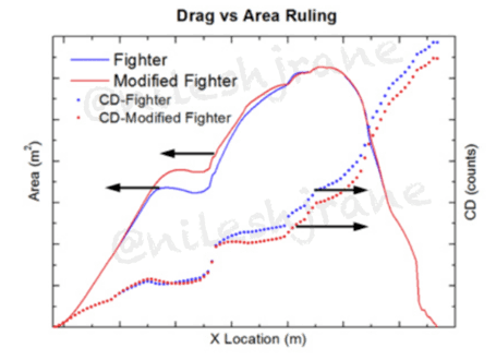
However, to meet the IAF’s stringent air staff qualitative requirements (ASQR) for the LCA project, ADA knew that substantial changes to the basic Mk1/Mk1A airframe were required and that is where the genesis of the Tejas Mk2 development program lies. There were two primary concerns: the IAF wanted a fighter that had faster transonic acceleration and a higher STR of about 18 degrees per second. As late as Aero India 2017, ADA displayed scale models that aimed to achieve this by extending the Mk1 with a 0.5 m fuselage plug and fitting a more powerful F414 engine with a maximum rated thrust of 98kN. The plug was to be inserted just behind the canopy where the area curve had the highest discontinuity (see Area curve in Figure 2). In addition to the plug, ADA studied a bulged canopy to improve area ruling even further. The combined effect was 6 percent lower supersonic drag, which in turn led to a 20 percent improvement in transonic acceleration and 2 percent improvement in maximum speed [4]. The fuselage plug and bulged spine would also provide space for more internal fuel and LRUs.


Figure 2: Canopy optimization study shows a bulged canopy improving the area ruling results in 6% reduction in drag, 20% increase in transonic acceleration and 2% increase in max speed[4].

Similarly, it was observed that there was a sudden kink in the aft bottom of the fuselage in Mk1 as shown in Figure 3. By eliminating this kink and identifying an optimized smoothened aft fuselage, an improvement of 4.9 percent was predicted in the supersonic drag on the aft body region.


Figure 3: Assessment of aft body optimization for supersonic drag reduction. Comparison of Surface Cp contours near the aft region for base configuration and that of optimized aft region at M=1.2, AoA= 3 [cite].

Besides clean configurations, studies were also conducted to decrease the drag of loaded configurations. For example, it was realized early that by replacing the current ‘blunt’ pylons on Mk1 with more aerodynamically shaped pylons, significant drag reduction could be affected in supersonic regimes[18]. Figure 4 shows the inboard pylons before and after the reshaping. These new pylons have already been realized and are expected to even become a part of the MK1/1A platforms. One such pylon for the center fuselage has been put on display in Aero India 2019.


Figure 4: wing inboard pylon: before and after reshaping for better supersonic drag [18].

Similarly, computation fluid dynamics (CFD) studies on a variety of drop tanks have yielded fuel tank geometries which could carry more fuel at marginal to no extra cost in drag. For example, Figure 5 shows the modified supersonic drop tank arrived by choosing optimal lengths for the conical nose and tail sections. The final shape allowed the carriage of 58 percent more fuel (710 L against the current 450 L) at only two counts greater supersonic drag. This provided a significant increase of about 11 percent in flight mission time. This tank can also be seen at Aero India 2019.


Figure 5: Modified supersonic drop tank with 58% more fuel carrying capacity and 2 counts increase in supersonic drag.


Figure 6: Effect of drop tanks, original and modified on airlfow around nearby bombs. The modified drop tanks has negligible destabilizing effect, 11% more fuel carrying capacity and lower drag penalty.


Besides the supersonic tanks, it was found that the presence of the current 1200 L subsonic fuel tank generates a suction on the surface of a bomb placed on its nearby station. This asymmetric force led to the destabilization of the bomb, and deviation from its ideal separation trajectory. Therefore, a variety of alternate geometries were studied which could mitigate this problem. The resultant fuel tank not only had a trivial destabilizing moment as shown in Figure 6 but could carry 11 percent more fuel at a lower drag penalty. These reshaped tanks are estimated to provide a 15-18 percent improvement in mission performance and will also be retrofitted on the Mk1/1A.


Detailed studies were carried out on the aerodynamic characteristics of CCM carriage at wing tip stations rather than the underwing station, as in the Mk1. The CFD studies found that carrying a CCM at the wingtip station increased lift-to-drag (L/D ratio) in subsonic, transonic and supersonic regions. Additionally, the fighter with the wingtip stations exhibited better Cnβ characteristics which would aid in the higher AoA flight regimes.


Figure 7: Assessment of Wintip mounted vs underwing CCM pylon. CFD study shows significant improvement in Zero-Lift drag at all speeds, especially the supersonic regime [5]


Figure 8: Wingtip mounted CCM pylon improved aerodynamic efficiency (L/D ration) of the wing significantly at all speeds and especially at the supersonic speeds [5]


Other means of increasing directional stability at higher AoA included studies of body strakes of different geometries at different fuselage locations as shown in Figure 9. Various geometries were found which could improve the yaw moment coefficient (Cnβ) by energizing the wing vortex, but at the cost of pitching characteristics. Therefore, subsequent studies were carried out using a chine (nose strake) to improve Cnβ with a focus on its influence on undesired pitching characteristics. The best chine gave a marked improvement in Cnβ by anchoring the nose vortex flow with only a marginal effect on pitching coefficient [8].


Figure 8: Fuselage and nose strakes (chine) studied for improvements in Cnβ [8]


A substantial amount of effort was directed towards optimizing the air intakes. The impact of changes in lip and cowl geometries, contractions ratio (i.e. the ratio of air intake to the minimum area of the intake duct) and performance of a newly proposed 3-door auxiliary intake were studied. The goal of these studies was to improve pressure recovery at low speeds without adversely impacting spillage drag at high speeds. It was found that the lip geometry and variation in contraction ratio of these features have minor improvements in low speed regimes, but their attendant side effect on high speed performance was deemed to be too high. On the other hand, cowl geometry optimization showed good improvement in pressure recovery due to its positive impact on the local flow field near the inlet plane. The 3-door design further enhances the gains in pressure recovery. It’s also expected to facilitate improved flow rates through the auxiliary intakes during the low speed, high AoA regimes. The combination of optimized cowl geometry and 3-door design results in a 3 percent improvement in pressure recovery, which should lead to an equivalent improvement in engine performance [11]. The 3-door design can already be seen on LCA Navy Mk1 prototypes.


Figure 9: Streamlines showing airflow through Auxiliary Air Intake Doors (AAID) at low speeds. Top image represents existing design on LCA MK1. Bottom design is proposed 3-door design for improved airflow at low speed [11].


With the above-mentioned changes, the Tejas Mk2 was predicted to have significantly lower transonic and supersonic drag, even with a slight increase in weight. Coupled with a more powerful engine, this variant would have much improved transonic and supersonic performance. The higher thrust engine also accorded a higher TWR which when combined with the better L/D, meant the fighter would have a better turn rate and a higher climb rate. The fuselage plug ensured additional space for more internal fuel and an internal SPJ. This, in turn, would lead to higher endurance and range. All in all, ADA was suggesting changes which could have been designed, built, flight tested and certified within a relatively short period of time.


However, on account of the IAF’s growing requirements, ADA is now engrossed in the creation of a substantially more capable and larger Mk2 design, which has since been dubbed the Medium Weight Fighter (MWF) and will be the focus of the next part of this series.


Indranil Roy is an aircraft enthusiast and a part time processor chip designer.

Nilesh J. Rane is an aviation geek by passion and aerospace engineer by profession.


References:


    • HAL RFI documents for LCA Mk2 fuselage sections, obtained from HAL Website.
    • “An assessment of effects of Canard Sweep angle on the Longitudinal Aerodynamics of Delta wing aircraft”, 19th CFD Symposium, Bangalore, 2017.
    • “Influence of Canopy shape on the supersonic drag of a generic Fighter Aircraft”, 17th Annual CFD Symposium, Bangalore, India, 2015.
    • “Aerodynamic characteristics of a Generic Fighter aircraft with Air-to-Air missiles carried at Underwing station vis-a-vis Wing Tip”, 19th CFD Symposium, Bangalore, 2017.
    • “Effect of arrangement of weapons on Zero lift drag of an Aircraft”, 18th Annual CFD Symposium, Bangalore, India, 2016.
    • “CFD studies of a Supersonic drop tank for a generic fighter aircraft”, 17th Annual CFD Symposium, Bangalore, India, 2015.
    • “CFD studies with nose chine and fuselage strake on a generic fighter aircraft”, 18th Annual CFD Symposium, Bangalore, India, 2016.
    • “Design of fuel tank for a generic fighter aircraft constrained by its influence on neighboring store”, 18th Annual CFD Symposium, Bangalore, India, 2016.
    • Aft body optimization of a generic fighter aircraft for supersonic drag reduction”, 18th Annual CFD Symposium, Bangalore, India, 2016.
    • “Intake Performance studies for a generic fighter aircraft configuration”, 18th Annual CFD Symposium, Bangalore, India, 2016.
    • Kota Harinarayana – “I believe it would have far superior range and capabilities than the Mirage 2000.” From interview in Aeromag Asia, May-June 2018, Vol12, issue3
    • “Aircraft Performance Improvements-A Practical Approach”, S.K. Jebakumar, DRDO Science Spectrum, March 2009.
    • “Effect of Arrangement of Weapons on Zero-Lift Drag of an Aircraft”,18th Annual CFD Symposium, August 10-11, 2016.
© Delhi Defence Review.

https://www.google.com/amp/delhidef...gn-evolution-of-an-indian-fighter-part-i/amp/


AbRaj

New Member
Joined
Jan 22, 2016
Messages
1,051
Likes
1,782
Country flag
They not Stretched To there Limits And Load Combinations You Need Certifications for each

Majority F-16's blocks Got FOC Decade's Ago That Is why its Figures are Available openly For Analysis

LCA Actual performance specs Will Be openly available in next 5-6 years When its Fully operational

And Indicator Will be FOC variant
Curious to know if you are using different formula that used conventionally for TWR calculations.
I have seen that catchphrase multiple times on paki forums .
Does that mean we have enhanced the thrust rating of GE404 ?
Or we reduced the weight of LCA drastically.
I cant find evidences of any of the above.
 

WARREN SS

New Member
Joined
Oct 12, 2013
Messages
5,570
Likes
20,878
Country flag
Curious to know if you are using different formula that used conventionally for TWR calculations.
I have seen that catchphrase multiple times on paki forums .
Does that mean we have enhanced the thrust rating of GE404 ?
Or we reduced the weight of LCA drastically.
I cant find evidences of any of the above.
No It Means Flying Weapon With full Payload And Full internal fuel
And drop tanks
Difference BTW and Empty and loaded weight

Twr Differnce btw Air To Ground Mission And Air to Air Load-weight
 

WARREN SS

New Member
Joined
Oct 12, 2013
Messages
5,570
Likes
20,878
Country flag
Just curious to know from where the 1.07 figure came from???
@HariPrasad-1 posted for this query
@AbRaj

For your information. Go through this article containing extract of that researcher paper which is not available now. Here aerodynamics is discussed in detail. I have removed many images as not more than 8 images are allowed to be posted here. So follow the link for details.

  • Indranil Roy & Nilesh Rane
  • 1 year ago
Tracking The Tejas: The Design Evolution Of An Indian Fighter Part-I

It is no overstatement to say that the Tejas Light Combat Aircraft (LCA) program has made significant progress of late with the Mk1 variant being officially granted Final Operational Clearance (FOC) on February 20, 2019 and its production picking up pace at Hindustan Aeronautics Limited (HAL). Seven of the thirteen Initial Operational Clearance (IOC) standard Tejas Mk1 already in service with No. 45 squadron or the Flying Daggers of the Indian Air Force (IAF) were handed over in the last 11 months alone. The remaining three IOC-standard single-seater aircraft meant for the Flying Daggers are slated to join the squadron by the end of April 2019. The Tejas MK1 is now also a regular at IAF air exercises, raking up high range scores and generally winning the confidence of its users. As such, the focus has now shifted to the development and production of the Tejas Mk1A variant since India’s Defence Acquisition Council has accorded approval for the acquisition of 83 units of the type by the IAF. Before we turn to analyzing developments related to the Mk1A and further evolution of the Tejas platform, it is important to profile the current capabilities of the baseline Mk1 itself.


LCA Tejas Mk1
Tejas Mk1 is a ‘fourth-generation lightweight, single-engine, multi-role, tactical fighter aircraft. It employs an unstable tailless compound delta-wing configuration, optimized primarily for maneuverability and agility’. Over 90 percent of its surface, and over 45 percent of its airframe by weight is made of composite structures. This is one of the highest usage of composites in an aircraft of any kind, anywhere in the world. This extensive use of composites has lowered the aircraft’s weight by 21 percent and reduced its part count by 40 percent, as opposed to what would have been the case had it been of all-metal construction.


The aircraft has intentionally been made longitudinally unstable to enhance maneuverability. In fact, its static margin, i.e. a measure of its instability (and hence maneuverability) is also one of the highest for any modern fighter aircraft [18]. To recover stability and provide good handling qualities, it is equipped with a fully redundant quadruplex digital fly-by-wire flight control system (FCS). This FCS is one of the biggest accomplishments of the LCA program. Its robustness has ensured an accident-free test record of over 4,300 test flights. The aircraft has also been equipped with advanced autopilot capabilities like auto-level (in case of pilot disorientation), safe altitude recovery (which automatically pulls up the aircraft if it comes too close to the ground) and auto navigation modes.


In-service aircraft are certified to fly from -3.5 to +8.0 Gs, up to an altitude of 50,000 feet, a top speed of Mach 1.6, and an angle of attack (AoA) of up to 24 degrees. The test pilots have stretched the prototypes even further, up to 8.5 Gs, and 26 degrees AoA. At the 2016 Bahrain Air Show, the Mk1 had even demonstrated a low speed pass at 110 knots. The FCS has now been updated to lower the minimum speed to 100 knots, at which point auto recovery is initiated. The 2016 demonstration at Bahrain also showcased another important feature: Following the above-mentioned low speed pass the aircraft immediately proceeded to accomplish a vertical climb. The ability to accelerate while in a climb is a virtue that only fighters with a thrust to weight ratio (TWR) of above 1.0 possess. At Bahrain, the Mk1 also showcased an instantaneous turn rate (ITR) of near 30 degrees per second and a sustained turn rate (STR) of between 15 to 16 degrees per second. A minimum radius turn of 350 metres (m) radius was also exhibited. All of these are extremely respectable numbers for air to air (A2A) combat roles.


The Mk1 is equipped with a powerful MultiMode Radar (MMR) which has A2A, air to sea, and air to ground (A2G) target detection modes. In A2A, the Tejas Mk1 is currently capable of firing R-73 close combat missiles (CCMs) and Derby beyond visual range A2A missiles (BVRAAMs). In the future, the Mk1 is likely to be integrated with India’s Astra BVRAAM as well. Together, with state-of-the-art helmet mounted display and sight (HMDS) and hands on throttle-and-stick (HOTAS) controls, and coupled with navigation aides like Very High-Frequency (VHF) Omnidirectional Range (VOR) / Instrument Landing System (ILS) and tactical air navigation system (TACAN), Tejas Mk1 allows the pilot to concentrate on “head-down” mission-critical requirements rather than worry about basic flying.


One of the Tejas’s greatest strengths is its A2G weapon delivery accuracy. In all flight tests and air exercises so far, the Mk1 has consistently garnered some of the highest range scores of all the aircraft in the IAF’s inventory. Not only can it carry 250 kg and 450 kg dumb bombs, but also laser guided bombs (LGBs) which are guided to their targets using a Litening laser designation pod (LDP). A single LGB can be carried on either the center-fuselage, wing-inboard or midboard weapon stations. For dumb bombs, two can be carried in tandem in the wing-inboard pylons, whereas one each can be carried in the center-fuselage and wing-midboard locations.


The Mk1’s all-weather and day/night capability has been proven in various extreme hot and cold weather trials, from Jaisalmer to Leh. For example, in Leh, the aircraft was successfully started after a cold soak of 42 hours where the temperature reached near -20°C . In each of the three attempts, the aircraft started effortlessly even on a partially drained battery. The reader might be reminded that a few Multi-Medium Role Combat Aircraft (MMRCA) contestants had actually failed this test during trials for that tender. Similarly, in hot and high trials, the aircraft took off with 1.9 tons (50 percent) of its max payload, which is an astounding feet given its highly swept delta wings.


The Tejas Mk1 has a total of five ‘wet’ points: one underneath the fuselage and two underneath each wing. The hardpoint underneath the fuselage can carry a 725 litre (L) subsonic drop tank or a 710 L supersonic tank (still under development). The wing inboard pylon can carry a subsonic drop tank of 1200 L while the midboard can carry a drop tank of 800 L. Although the MK-1’s developer, the Aeronautical Development Agency (ADA) publishes a conservative ferry range of 1750 km, ferry flights of ranges of nearly 2100 km have been completed in the past. The FOC version of the Tejas MK-1 has also been fitted with a fixed refueling probe which can be used to refill all of it internal and external fuel tanks, effectively doubling its range and endurance.


Enter the Tejas Mk1A
Now even while ADA was developing the Tejas Mk2 for the IAF, HAL proposed a simpler interim upgrade. Thus emerged the Tejas Mk1A which will be equipped with an ELTA EL/M- 2052 active electronic scanned array (AESA) radar along with a compatible electronic warfare suite, which would include a self protection jammer (SPJ) pod carried on the outboard wing pylon. This position was found to derive maximum performance out of the pod. On the the outboard pylon, two CCMs would be carried on a dual-rack pylon as shown in Figure 1. This configuration was found to have lowest drag penalties among a variety of studied configurations [19].


In addition to the above changes, HAL would upgrade some line replacement units (LRUs) to cater to obsolescence management, weight reduction, ease of manufacture and maintenance. The aircraft would also be fitted with an Onboard Oxygen Generation System (OBOGS) which would allow pilots to undertake long endurance flights. The turnaround time of the aircraft has also been reduced by means of hot refueling, a feature that SAAB wanted to showcase on its Gripen fighter during the MMRCA competition. At the time, the permission was denied by the IAF since it did not have a standard operational procedure (SOP) set up for the same. This hot refueling capability has now been showcased on a Tejas test aircraft.


Figure 1: One jammer and a twin-assembly of two CCMs at the O/B stations of the aircraft [19].


The initial road to the Mk2
However, to meet the IAF’s stringent air staff qualitative requirements (ASQR) for the LCA project, ADA knew that substantial changes to the basic Mk1/Mk1A airframe were required and that is where the genesis of the Tejas Mk2 development program lies. There were two primary concerns: the IAF wanted a fighter that had faster transonic acceleration and a higher STR of about 18 degrees per second. As late as Aero India 2017, ADA displayed scale models that aimed to achieve this by extending the Mk1 with a 0.5 m fuselage plug and fitting a more powerful F414 engine with a maximum rated thrust of 98kN. The plug was to be inserted just behind the canopy where the area curve had the highest discontinuity (see Area curve in Figure 2). In addition to the plug, ADA studied a bulged canopy to improve area ruling even further. The combined effect was 6 percent lower supersonic drag, which in turn led to a 20 percent improvement in transonic acceleration and 2 percent improvement in maximum speed [4]. The fuselage plug and bulged spine would also provide space for more internal fuel and LRUs.


Figure 2: Canopy optimization study shows a bulged canopy improving the area ruling results in 6% reduction in drag, 20% increase in transonic acceleration and 2% increase in max speed[4].

Similarly, it was observed that there was a sudden kink in the aft bottom of the fuselage in Mk1 as shown in Figure 3. By eliminating this kink and identifying an optimized smoothened aft fuselage, an improvement of 4.9 percent was predicted in the supersonic drag on the aft body region.


Figure 3: Assessment of aft body optimization for supersonic drag reduction. Comparison of Surface Cp contours near the aft region for base configuration and that of optimized aft region at M=1.2, AoA= 3 [cite].

Besides clean configurations, studies were also conducted to decrease the drag of loaded configurations. For example, it was realized early that by replacing the current ‘blunt’ pylons on Mk1 with more aerodynamically shaped pylons, significant drag reduction could be affected in supersonic regimes[18]. Figure 4 shows the inboard pylons before and after the reshaping. These new pylons have already been realized and are expected to even become a part of the MK1/1A platforms. One such pylon for the center fuselage has been put on display in Aero India 2019.


Figure 4: wing inboard pylon: before and after reshaping for better supersonic drag [18].

Similarly, computation fluid dynamics (CFD) studies on a variety of drop tanks have yielded fuel tank geometries which could carry more fuel at marginal to no extra cost in drag. For example, Figure 5 shows the modified supersonic drop tank arrived by choosing optimal lengths for the conical nose and tail sections. The final shape allowed the carriage of 58 percent more fuel (710 L against the current 450 L) at only two counts greater supersonic drag. This provided a significant increase of about 11 percent in flight mission time. This tank can also be seen at Aero India 2019.


Figure 5: Modified supersonic drop tank with 58% more fuel carrying capacity and 2 counts increase in supersonic drag.


Figure 6: Effect of drop tanks, original and modified on airlfow around nearby bombs. The modified drop tanks has negligible destabilizing effect, 11% more fuel carrying capacity and lower drag penalty.


Besides the supersonic tanks, it was found that the presence of the current 1200 L subsonic fuel tank generates a suction on the surface of a bomb placed on its nearby station. This asymmetric force led to the destabilization of the bomb, and deviation from its ideal separation trajectory. Therefore, a variety of alternate geometries were studied which could mitigate this problem. The resultant fuel tank not only had a trivial destabilizing moment as shown in Figure 6 but could carry 11 percent more fuel at a lower drag penalty. These reshaped tanks are estimated to provide a 15-18 percent improvement in mission performance and will also be retrofitted on the Mk1/1A.


Detailed studies were carried out on the aerodynamic characteristics of CCM carriage at wing tip stations rather than the underwing station, as in the Mk1. The CFD studies found that carrying a CCM at the wingtip station increased lift-to-drag (L/D ratio) in subsonic, transonic and supersonic regions. Additionally, the fighter with the wingtip stations exhibited better Cnβ characteristics which would aid in the higher AoA flight regimes.


Figure 7: Assessment of Wintip mounted vs underwing CCM pylon. CFD study shows significant improvement in Zero-Lift drag at all speeds, especially the supersonic regime [5]


Figure 8: Wingtip mounted CCM pylon improved aerodynamic efficiency (L/D ration) of the wing significantly at all speeds and especially at the supersonic speeds [5]


Other means of increasing directional stability at higher AoA included studies of body strakes of different geometries at different fuselage locations as shown in Figure 9. Various geometries were found which could improve the yaw moment coefficient (Cnβ) by energizing the wing vortex, but at the cost of pitching characteristics. Therefore, subsequent studies were carried out using a chine (nose strake) to improve Cnβ with a focus on its influence on undesired pitching characteristics. The best chine gave a marked improvement in Cnβ by anchoring the nose vortex flow with only a marginal effect on pitching coefficient [8].


Figure 8: Fuselage and nose strakes (chine) studied for improvements in Cnβ [8]


A substantial amount of effort was directed towards optimizing the air intakes. The impact of changes in lip and cowl geometries, contractions ratio (i.e. the ratio of air intake to the minimum area of the intake duct) and performance of a newly proposed 3-door auxiliary intake were studied. The goal of these studies was to improve pressure recovery at low speeds without adversely impacting spillage drag at high speeds. It was found that the lip geometry and variation in contraction ratio of these features have minor improvements in low speed regimes, but their attendant side effect on high speed performance was deemed to be too high. On the other hand, cowl geometry optimization showed good improvement in pressure recovery due to its positive impact on the local flow field near the inlet plane. The 3-door design further enhances the gains in pressure recovery. It’s also expected to facilitate improved flow rates through the auxiliary intakes during the low speed, high AoA regimes. The combination of optimized cowl geometry and 3-door design results in a 3 percent improvement in pressure recovery, which should lead to an equivalent improvement in engine performance [11]. The 3-door design can already be seen on LCA Navy Mk1 prototypes.


Figure 9: Streamlines showing airflow through Auxiliary Air Intake Doors (AAID) at low speeds. Top image represents existing design on LCA MK1. Bottom design is proposed 3-door design for improved airflow at low speed [11].


With the above-mentioned changes, the Tejas Mk2 was predicted to have significantly lower transonic and supersonic drag, even with a slight increase in weight. Coupled with a more powerful engine, this variant would have much improved transonic and supersonic performance. The higher thrust engine also accorded a higher TWR which when combined with the better L/D, meant the fighter would have a better turn rate and a higher climb rate. The fuselage plug ensured additional space for more internal fuel and an internal SPJ. This, in turn, would lead to higher endurance and range. All in all, ADA was suggesting changes which could have been designed, built, flight tested and certified within a relatively short period of time.


However, on account of the IAF’s growing requirements, ADA is now engrossed in the creation of a substantially more capable and larger Mk2 design, which has since been dubbed the Medium Weight Fighter (MWF) and will be the focus of the next part of this series.


Indranil Roy is an aircraft enthusiast and a part time processor chip designer.

Nilesh J. Rane is an aviation geek by passion and aerospace engineer by profession.


References:


    • HAL RFI documents for LCA Mk2 fuselage sections, obtained from HAL Website.
    • “An assessment of effects of Canard Sweep angle on the Longitudinal Aerodynamics of Delta wing aircraft”, 19th CFD Symposium, Bangalore, 2017.
    • “Influence of Canopy shape on the supersonic drag of a generic Fighter Aircraft”, 17th Annual CFD Symposium, Bangalore, India, 2015.
    • “Aerodynamic characteristics of a Generic Fighter aircraft with Air-to-Air missiles carried at Underwing station vis-a-vis Wing Tip”, 19th CFD Symposium, Bangalore, 2017.
    • “Effect of arrangement of weapons on Zero lift drag of an Aircraft”, 18th Annual CFD Symposium, Bangalore, India, 2016.
    • “CFD studies of a Supersonic drop tank for a generic fighter aircraft”, 17th Annual CFD Symposium, Bangalore, India, 2015.
    • “CFD studies with nose chine and fuselage strake on a generic fighter aircraft”, 18th Annual CFD Symposium, Bangalore, India, 2016.
    • “Design of fuel tank for a generic fighter aircraft constrained by its influence on neighboring store”, 18th Annual CFD Symposium, Bangalore, India, 2016.
    • Aft body optimization of a generic fighter aircraft for supersonic drag reduction”, 18th Annual CFD Symposium, Bangalore, India, 2016.
    • “Intake Performance studies for a generic fighter aircraft configuration”, 18th Annual CFD Symposium, Bangalore, India, 2016.
    • Kota Harinarayana – “I believe it would have far superior range and capabilities than the Mirage 2000.” From interview in Aeromag Asia, May-June 2018, Vol12, issue3
    • “Aircraft Performance Improvements-A Practical Approach”, S.K. Jebakumar, DRDO Science Spectrum, March 2009.
    • “Effect of Arrangement of Weapons on Zero-Lift Drag of an Aircraft”,18th Annual CFD Symposium, August 10-11, 2016.
© Delhi Defence Review.

https://www.google.com/amp/delhidef...gn-evolution-of-an-indian-fighter-part-i/amp/


AbRaj

New Member
Joined
Jan 22, 2016
Messages
1,051
Likes
1,782
Country flag
NAVIGATE

  • Indranil Roy & Nilesh Rane
  • 1 year ago
Tracking The Tejas: The Design Evolution Of An Indian Fighter Part-I

It is no overstatement to say that the Tejas Light Combat Aircraft (LCA) program has made significant progress of late with the Mk1 variant being officially granted Final Operational Clearance (FOC) on February 20, 2019 and its production picking up pace at Hindustan Aeronautics Limited (HAL). Seven of the thirteen Initial Operational Clearance (IOC) standard Tejas Mk1 already in service with No. 45 squadron or the Flying Daggers of the Indian Air Force (IAF) were handed over in the last 11 months alone. The remaining three IOC-standard single-seater aircraft meant for the Flying Daggers are slated to join the squadron by the end of April 2019. The Tejas MK1 is now also a regular at IAF air exercises, raking up high range scores and generally winning the confidence of its users. As such, the focus has now shifted to the development and production of the Tejas Mk1A variant since India’s Defence Acquisition Council has accorded approval for the acquisition of 83 units of the type by the IAF. Before we turn to analyzing developments related to the Mk1A and further evolution of the Tejas platform, it is important to profile the current capabilities of the baseline Mk1 itself.


LCA Tejas Mk1
Tejas Mk1 is a ‘fourth-generation lightweight, single-engine, multi-role, tactical fighter aircraft. It employs an unstable tailless compound delta-wing configuration, optimized primarily for maneuverability and agility’. Over 90 percent of its surface, and over 45 percent of its airframe by weight is made of composite structures. This is one of the highest usage of composites in an aircraft of any kind, anywhere in the world. This extensive use of composites has lowered the aircraft’s weight by 21 percent and reduced its part count by 40 percent, as opposed to what would have been the case had it been of all-metal construction.


The aircraft has intentionally been made longitudinally unstable to enhance maneuverability. In fact, its static margin, i.e. a measure of its instability (and hence maneuverability) is also one of the highest for any modern fighter aircraft [18]. To recover stability and provide good handling qualities, it is equipped with a fully redundant quadruplex digital fly-by-wire flight control system (FCS). This FCS is one of the biggest accomplishments of the LCA program. Its robustness has ensured an accident-free test record of over 4,300 test flights. The aircraft has also been equipped with advanced autopilot capabilities like auto-level (in case of pilot disorientation), safe altitude recovery (which automatically pulls up the aircraft if it comes too close to the ground) and auto navigation modes.


In-service aircraft are certified to fly from -3.5 to +8.0 Gs, up to an altitude of 50,000 feet, a top speed of Mach 1.6, and an angle of attack (AoA) of up to 24 degrees. The test pilots have stretched the prototypes even further, up to 8.5 Gs, and 26 degrees AoA. At the 2016 Bahrain Air Show, the Mk1 had even demonstrated a low speed pass at 110 knots. The FCS has now been updated to lower the minimum speed to 100 knots, at which point auto recovery is initiated. The 2016 demonstration at Bahrain also showcased another important feature: Following the above-mentioned low speed pass the aircraft immediately proceeded to accomplish a vertical climb. The ability to accelerate while in a climb is a virtue that only fighters with a thrust to weight ratio (TWR) of above 1.0 possess. At Bahrain, the Mk1 also showcased an instantaneous turn rate (ITR) of near 30 degrees per second and a sustained turn rate (STR) of between 15 to 16 degrees per second. A minimum radius turn of 350 metres (m) radius was also exhibited. All of these are extremely respectable numbers for air to air (A2A) combat roles.


The Mk1 is equipped with a powerful MultiMode Radar (MMR) which has A2A, air to sea, and air to ground (A2G) target detection modes. In A2A, the Tejas Mk1 is currently capable of firing R-73 close combat missiles (CCMs) and Derby beyond visual range A2A missiles (BVRAAMs). In the future, the Mk1 is likely to be integrated with India’s Astra BVRAAM as well. Together, with state-of-the-art helmet mounted display and sight (HMDS) and hands on throttle-and-stick (HOTAS) controls, and coupled with navigation aides like Very High-Frequency (VHF) Omnidirectional Range (VOR) / Instrument Landing System (ILS) and tactical air navigation system (TACAN), Tejas Mk1 allows the pilot to concentrate on “head-down” mission-critical requirements rather than worry about basic flying.


One of the Tejas’s greatest strengths is its A2G weapon delivery accuracy. In all flight tests and air exercises so far, the Mk1 has consistently garnered some of the highest range scores of all the aircraft in the IAF’s inventory. Not only can it carry 250 kg and 450 kg dumb bombs, but also laser guided bombs (LGBs) which are guided to their targets using a Litening laser designation pod (LDP). A single LGB can be carried on either the center-fuselage, wing-inboard or midboard weapon stations. For dumb bombs, two can be carried in tandem in the wing-inboard pylons, whereas one each can be carried in the center-fuselage and wing-midboard locations.


The Mk1’s all-weather and day/night capability has been proven in various extreme hot and cold weather trials, from Jaisalmer to Leh. For example, in Leh, the aircraft was successfully started after a cold soak of 42 hours where the temperature reached near -20°C . In each of the three attempts, the aircraft started effortlessly even on a partially drained battery. The reader might be reminded that a few Multi-Medium Role Combat Aircraft (MMRCA) contestants had actually failed this test during trials for that tender. Similarly, in hot and high trials, the aircraft took off with 1.9 tons (50 percent) of its max payload, which is an astounding feet given its highly swept delta wings.


The Tejas Mk1 has a total of five ‘wet’ points: one underneath the fuselage and two underneath each wing. The hardpoint underneath the fuselage can carry a 725 litre (L) subsonic drop tank or a 710 L supersonic tank (still under development). The wing inboard pylon can carry a subsonic drop tank of 1200 L while the midboard can carry a drop tank of 800 L. Although the MK-1’s developer, the Aeronautical Development Agency (ADA) publishes a conservative ferry range of 1750 km, ferry flights of ranges of nearly 2100 km have been completed in the past. The FOC version of the Tejas MK-1 has also been fitted with a fixed refueling probe which can be used to refill all of it internal and external fuel tanks, effectively doubling its range and endurance.


Enter the Tejas Mk1A
Now even while ADA was developing the Tejas Mk2 for the IAF, HAL proposed a simpler interim upgrade. Thus emerged the Tejas Mk1A which will be equipped with an ELTA EL/M- 2052 active electronic scanned array (AESA) radar along with a compatible electronic warfare suite, which would include a self protection jammer (SPJ) pod carried on the outboard wing pylon. This position was found to derive maximum performance out of the pod. On the the outboard pylon, two CCMs would be carried on a dual-rack pylon as shown in Figure 1. This configuration was found to have lowest drag penalties among a variety of studied configurations [19].


In addition to the above changes, HAL would upgrade some line replacement units (LRUs) to cater to obsolescence management, weight reduction, ease of manufacture and maintenance. The aircraft would also be fitted with an Onboard Oxygen Generation System (OBOGS) which would allow pilots to undertake long endurance flights. The turnaround time of the aircraft has also been reduced by means of hot refueling, a feature that SAAB wanted to showcase on its Gripen fighter during the MMRCA competition. At the time, the permission was denied by the IAF since it did not have a standard operational procedure (SOP) set up for the same. This hot refueling capability has now been showcased on a Tejas test aircraft.


Figure 1: One jammer and a twin-assembly of two CCMs at the O/B stations of the aircraft [19].


The initial road to the Mk2
However, to meet the IAF’s stringent air staff qualitative requirements (ASQR) for the LCA project, ADA knew that substantial changes to the basic Mk1/Mk1A airframe were required and that is where the genesis of the Tejas Mk2 development program lies. There were two primary concerns: the IAF wanted a fighter that had faster transonic acceleration and a higher STR of about 18 degrees per second. As late as Aero India 2017, ADA displayed scale models that aimed to achieve this by extending the Mk1 with a 0.5 m fuselage plug and fitting a more powerful F414 engine with a maximum rated thrust of 98kN. The plug was to be inserted just behind the canopy where the area curve had the highest discontinuity (see Area curve in Figure 2). In addition to the plug, ADA studied a bulged canopy to improve area ruling even further. The combined effect was 6 percent lower supersonic drag, which in turn led to a 20 percent improvement in transonic acceleration and 2 percent improvement in maximum speed [4]. The fuselage plug and bulged spine would also provide space for more internal fuel and LRUs.


Figure 2: Canopy optimization study shows a bulged canopy improving the area ruling results in 6% reduction in drag, 20% increase in transonic acceleration and 2% increase in max speed[4].

Similarly, it was observed that there was a sudden kink in the aft bottom of the fuselage in Mk1 as shown in Figure 3. By eliminating this kink and identifying an optimized smoothened aft fuselage, an improvement of 4.9 percent was predicted in the supersonic drag on the aft body region.


Figure 3: Assessment of aft body optimization for supersonic drag reduction. Comparison of Surface Cp contours near the aft region for base configuration and that of optimized aft region at M=1.2, AoA= 3 [cite].

Besides clean configurations, studies were also conducted to decrease the drag of loaded configurations. For example, it was realized early that by replacing the current ‘blunt’ pylons on Mk1 with more aerodynamically shaped pylons, significant drag reduction could be affected in supersonic regimes[18]. Figure 4 shows the inboard pylons before and after the reshaping. These new pylons have already been realized and are expected to even become a part of the MK1/1A platforms. One such pylon for the center fuselage has been put on display in Aero India 2019.


Figure 4: wing inboard pylon: before and after reshaping for better supersonic drag [18].

Similarly, computation fluid dynamics (CFD) studies on a variety of drop tanks have yielded fuel tank geometries which could carry more fuel at marginal to no extra cost in drag. For example, Figure 5 shows the modified supersonic drop tank arrived by choosing optimal lengths for the conical nose and tail sections. The final shape allowed the carriage of 58 percent more fuel (710 L against the current 450 L) at only two counts greater supersonic drag. This provided a significant increase of about 11 percent in flight mission time. This tank can also be seen at Aero India 2019.


Figure 5: Modified supersonic drop tank with 58% more fuel carrying capacity and 2 counts increase in supersonic drag.


Figure 6: Effect of drop tanks, original and modified on airlfow around nearby bombs. The modified drop tanks has negligible destabilizing effect, 11% more fuel carrying capacity and lower drag penalty.


Besides the supersonic tanks, it was found that the presence of the current 1200 L subsonic fuel tank generates a suction on the surface of a bomb placed on its nearby station. This asymmetric force led to the destabilization of the bomb, and deviation from its ideal separation trajectory. Therefore, a variety of alternate geometries were studied which could mitigate this problem. The resultant fuel tank not only had a trivial destabilizing moment as shown in Figure 6 but could carry 11 percent more fuel at a lower drag penalty. These reshaped tanks are estimated to provide a 15-18 percent improvement in mission performance and will also be retrofitted on the Mk1/1A.


Detailed studies were carried out on the aerodynamic characteristics of CCM carriage at wing tip stations rather than the underwing station, as in the Mk1. The CFD studies found that carrying a CCM at the wingtip station increased lift-to-drag (L/D ratio) in subsonic, transonic and supersonic regions. Additionally, the fighter with the wingtip stations exhibited better Cnβ characteristics which would aid in the higher AoA flight regimes.


Figure 7: Assessment of Wintip mounted vs underwing CCM pylon. CFD study shows significant improvement in Zero-Lift drag at all speeds, especially the supersonic regime [5]


Figure 8: Wingtip mounted CCM pylon improved aerodynamic efficiency (L/D ration) of the wing significantly at all speeds and especially at the supersonic speeds [5]


Other means of increasing directional stability at higher AoA included studies of body strakes of different geometries at different fuselage locations as shown in Figure 9. Various geometries were found which could improve the yaw moment coefficient (Cnβ) by energizing the wing vortex, but at the cost of pitching characteristics. Therefore, subsequent studies were carried out using a chine (nose strake) to improve Cnβ with a focus on its influence on undesired pitching characteristics. The best chine gave a marked improvement in Cnβ by anchoring the nose vortex flow with only a marginal effect on pitching coefficient [8].


Figure 8: Fuselage and nose strakes (chine) studied for improvements in Cnβ [8]


A substantial amount of effort was directed towards optimizing the air intakes. The impact of changes in lip and cowl geometries, contractions ratio (i.e. the ratio of air intake to the minimum area of the intake duct) and performance of a newly proposed 3-door auxiliary intake were studied. The goal of these studies was to improve pressure recovery at low speeds without adversely impacting spillage drag at high speeds. It was found that the lip geometry and variation in contraction ratio of these features have minor improvements in low speed regimes, but their attendant side effect on high speed performance was deemed to be too high. On the other hand, cowl geometry optimization showed good improvement in pressure recovery due to its positive impact on the local flow field near the inlet plane. The 3-door design further enhances the gains in pressure recovery. It’s also expected to facilitate improved flow rates through the auxiliary intakes during the low speed, high AoA regimes. The combination of optimized cowl geometry and 3-door design results in a 3 percent improvement in pressure recovery, which should lead to an equivalent improvement in engine performance [11]. The 3-door design can already be seen on LCA Navy Mk1 prototypes.


Figure 9: Streamlines showing airflow through Auxiliary Air Intake Doors (AAID) at low speeds. Top image represents existing design on LCA MK1. Bottom design is proposed 3-door design for improved airflow at low speed [11].


With the above-mentioned changes, the Tejas Mk2 was predicted to have significantly lower transonic and supersonic drag, even with a slight increase in weight. Coupled with a more powerful engine, this variant would have much improved transonic and supersonic performance. The higher thrust engine also accorded a higher TWR which when combined with the better L/D, meant the fighter would have a better turn rate and a higher climb rate. The fuselage plug ensured additional space for more internal fuel and an internal SPJ. This, in turn, would lead to higher endurance and range. All in all, ADA was suggesting changes which could have been designed, built, flight tested and certified within a relatively short period of time.


However, on account of the IAF’s growing requirements, ADA is now engrossed in the creation of a substantially more capable and larger Mk2 design, which has since been dubbed the Medium Weight Fighter (MWF) and will be the focus of the next part of this series.


Indranil Roy is an aircraft enthusiast and a part time processor chip designer.

Nilesh J. Rane is an aviation geek by passion and aerospace engineer by profession.


References:


    • HAL RFI documents for LCA Mk2 fuselage sections, obtained from HAL Website.
    • “An assessment of effects of Canard Sweep angle on the Longitudinal Aerodynamics of Delta wing aircraft”, 19th CFD Symposium, Bangalore, 2017.
    • “Influence of Canopy shape on the supersonic drag of a generic Fighter Aircraft”, 17th Annual CFD Symposium, Bangalore, India, 2015.
    • “Aerodynamic characteristics of a Generic Fighter aircraft with Air-to-Air missiles carried at Underwing station vis-a-vis Wing Tip”, 19th CFD Symposium, Bangalore, 2017.
    • “Effect of arrangement of weapons on Zero lift drag of an Aircraft”, 18th Annual CFD Symposium, Bangalore, India, 2016.
    • “CFD studies of a Supersonic drop tank for a generic fighter aircraft”, 17th Annual CFD Symposium, Bangalore, India, 2015.
    • “CFD studies with nose chine and fuselage strake on a generic fighter aircraft”, 18th Annual CFD Symposium, Bangalore, India, 2016.
    • “Design of fuel tank for a generic fighter aircraft constrained by its influence on neighboring store”, 18th Annual CFD Symposium, Bangalore, India, 2016.
    • Aft body optimization of a generic fighter aircraft for supersonic drag reduction”, 18th Annual CFD Symposium, Bangalore, India, 2016.
    • “Intake Performance studies for a generic fighter aircraft configuration”, 18th Annual CFD Symposium, Bangalore, India, 2016.
    • Kota Harinarayana – “I believe it would have far superior range and capabilities than the Mirage 2000.” From interview in Aeromag Asia, May-June 2018, Vol12, issue3
    • “Aircraft Performance Improvements-A Practical Approach”, S.K. Jebakumar, DRDO Science Spectrum, March 2009.
    • “Effect of Arrangement of Weapons on Zero-Lift Drag of an Aircraft”,18th Annual CFD Symposium, August 10-11, 2016.
© Delhi Defence Review.

https://www.google.com/amp/delhidef...gn-evolution-of-an-indian-fighter-part-i/amp/


@HariPrasad-1 lets hope for the best. But don’t expect too much.
No It Means Flying Weapon With full Payload And Full internal fuel
And drop tanks
Difference BTW and Empty and loaded weight

Twr Differnce btw Air To Ground Mission And Air to Air Load-weight
I learn new things on this forum every day. New ways to boost TWR using drop tanks is the newest.:biggrin2:
 

WARREN SS

New Member
Joined
Oct 12, 2013
Messages
5,570
Likes
20,878
Country flag
I learn new things on this forum every day. New ways to boost TWR using drop tanks is the newest
There Nothing To boost
Its Weight Which Effects Every thing not Thrust

  • Drop tanks Effect Net Weight ratio
  • How Filling You Internal tanks 50 % Effects TWR( F-16 increase From 1.095 To 1.24)
  • Difference BTW A-to-G vs A-to-A TWR
 

AbRaj

New Member
Joined
Jan 22, 2016
Messages
1,051
Likes
1,782
Country flag
There Nothing To boost
Its Weight Which Effects Every thing not Thrust

  • Drop tanks Effect Net Weight ratio
  • How Filling You Internal tanks 50 % Effects TWR( F-16 increase From 1.095 To 1.24)
  • Difference BTW A-to-G vs A-to-A
Drop tanks are included in the empty weight nowadays I guess. How many drop tanks are included wale calculating the twr?
Or filled up or 50% any any othe new criteria?

Do ammunition like lgbs and ugbs are also included? If yes how many?
 

Immanuel

New Member
Joined
May 16, 2011
Messages
3,605
Likes
7,574
Country flag
I never said otherwise. Block 52 that pakis have is fair game specially in BVR fight.


Never doubted the second part. Not happy about the outcome of 27 doesn’t mean doubting IAF pilots caliber at all. A driver (let’s say Michael schoonmaker) is as good as the car he is driving. He can’t win F1 with Ford Figo.
It was just one bad day.


As someone said somewhere else

In a 1v1 fight between F-16 Block 50/52 vs LCA Mk1A, the Mk1A will trump over the F-16 in BVR every time. Mk1A's advantages are the AESA radar, superior BVR (I-Derby ER, Derby is just a stopgap missile because we had some stocks of it bought for the Sea Harrier upgrade) and much lower RCS (as much as 12 times difference at the minimum). Performance differences in BVR should be more or less the same. In WVR, the Mk1A has a superior weapon with the ASRAAM and HMDS, but inferior performance, so it shouldn't get into a turning fight. The LCA only has an advantage in the first 30 seconds or so of a dog fight due to its higher instantaneous turn rate and HMDS+missile combo. If the missile doesn't do its job, then it's time to run. Only the Block 70 with the Aim-260 will be able to take the BVR advantage, while the WVR fight will see the same constraints for both aircraft.

In recce and strike missions, the F-16 takes home the cake. Superior endurance and payload makes it a far superior aircraft. LCA is only suitable for standoff strike (with Bhramos-M/Nirbhay etc), light strike and CAS. F-16 is capable of DPS along with everything else the LCA does. Plus it can escort itself.

In terms of cost, the F-16 beats the LCA even though the F-16 has a higher sticker price. Let's not forget that new build F-16s have a 12000-hour airframe life, while LCA Mk1 has 3000 hours and Mk1A should increase that to 4000 hours. If we are lucky, it may possibly be increased to 6000 hours by the time it comes in for an overhaul. So the overall LCC of the F-16 will be lower.

The LCA Mk1/Mk1A is a Mig-21 replacement, nothing more. Its minimalist design is its biggest drawback and can be fixed only on the MWF. Its primary function is air defence, as an interceptor, CAP or escort. And it will likely do CAS rather than anything else as a secondary mission. I dare say the only reason IAF is buying the 83 new jets is because they are in trouble with respect to squadron strength and it's the only available jet to replace the Mig-21.

@Bleh I’m not saying he is authentic but most of the times, I find him reasonably accurate.
F1 is where you compare, apples vs apples. It is silly compare the Tejas MK-1A to an F-16 both are different weight categories. LCA being light and F-16 being Medium. LCA has always been a Mig-21 replacement and will be a great replacement. LCA can be compared really to the JF Blunder.

MK1A will be lighter than the MK-1, overall performance should be better. The Block 70 is a lot heavier but it's also silly to compare this (Pak won't have), again the F-16 is well known, any respectable Indian pilot can run circles around it, especially since the LCA is visually hard to track in a dogfight (again I'll bet my odds on the LCA). The odds that a block 70 (which is not even produced yet) goes up against the LCA is very low.

Would be interesting to send the LCA to Redflag to see how it copes.
 

WARREN SS

New Member
Joined
Oct 12, 2013
Messages
5,570
Likes
20,878
Country flag
Drop tanks are included in the empty weight nowadays days I guess. How many drop tanks are included wale calculating the twr?
Or filled up or 50% any any othe new criteria?
Empty Weight only Counts Internal Fuel

Its Not New Criteria Its only changes Calculation criteria
 

AbRaj

New Member
Joined
Jan 22, 2016
Messages
1,051
Likes
1,782
Country flag
F1 is where you compare, apples vs apples. It is silly compare the Tejas MK-1A to an F-16 both are different weight categories. LCA being light and F-16 being Medium. LCA has always been a Mig-21 replacement and will be a great replacement. LCA can be compared really to the JF Blunder.

MK1A will be lighter than the MK-1, overall performance should be better. The Block 70 is a lot heavier but it's also silly to compare this (Pak won't have), again the F-16 is well known, any respectable Indian pilot can run circles around it, especially since the LCA is visually hard to track in a dogfight (again I'll bet my odds on the LCA). The odds that a block 70 (which is not even produced yet) goes up against the LCA is very low.

Would be interesting to send the LCA to Redflag to see how it copes.
You understood quickly What I was trying to say. For some it’s a tough task.
But LCA will not go down without a fight. It’s not a dud, far from it.
 

Articles

Top