Arjun vs T90 MBT

ersakthivel

Brilliance
New Member
Joined
Mar 6, 2011
Messages
7,029
Likes
8,764
Country flag
So photoshop people and 3D max people are welcome to analyze these views on perspective drawing in a scholarly manner ,

See, I respect PMAITRA's word and despite all the taunts I have done my best to carry foprward the debate in a technical way, Now PMAITRA

it is your responsibility to ban the guys who want to use foul language continuously without any provocation from my side.
 

pmaitra

New Member
Joined
Mar 10, 2009
Messages
33,262
Likes
19,600
^^

Report posts with foul language, and someone from staff will take action.
 

STGN

New Member
Joined
Jan 9, 2013
Messages
191
Likes
73


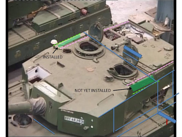
The shadow of the turret falls on the hull at the third blue line from the top.
it is the place where turret's side wall projection on the hull would fall.
The blue rectangle drawn on the TC's crew hatch cover represent s the true length of the hatch cover . True length? seems like you have oversized it.
This rectangle is projected in the correct plane on the hull ,
found out by the downwards projection of the line joining the two hatch covers on the turret top,
to the top of the hull.
This is the perspective drawing as far as I know, See below

If the side skirts are not included in the 3800 mm width of the hull the red line indicates that about half of the hatch cover length is the actual width besides the turret on the ARJUN hull.

IF the crew hatch measures 550mm it is about 275 mm.
SO the width of the turret is 3200 mm-(275x2=500 mm)=3300 mm,

If side skirts are included in the width about 4/5 th of the hatch cover length is the actual width besides the turret on the ARJUN hull.
That is about 0.80x550 mm=440 mm
3800-(400x2=880 mm)= 2900 mm is the width of the ARJUN turret. What is this are you being reasonable all of a sudden :shocked:

Even if you take a worst case scenario of 2900 mm turret width, Why worst?
1450mm is the distance between outter most side wall of arjun side turret and the turret centerline, Turret CL is not the middle of the turret but the axis that the turret rotates around
1200 mm is the distance between the two crew hatch centers,
1200/2= 600 mm is the distance of Tc' seat edge from the turret center line, turret is offset to the right side so this is not accurate calculation, the commander has more space than the loader
So 1450 mm-600 mm=850 mm is the space available besides the crew hatch center and the outer most side wall of arjun turrret,

If people agree on this point we can have an objective point.


E
This 850 mm is the distance between the outer turret wall of the arjun and the crew hatch hole center,
The two crew hatch holes are located at the same distance from the turret center line is my estimate,

SO even if we give out a margin of error of 200 mm in my estimate the space available for armor on the arjun's side turret wall is 650 mm.

Whether it is perspective drawing or perspektive drawing these rules are universal,
All objects must be projected to the apropriatre place to get any fair estimate,
The crew hatch covers are opened and standing vertically,.
The blue line joining the base of the two crew hatch covers represent the proper axis on which the covers are standing vertically,
SO if we have to project the width of the crew hatch cover to the correct position on the hull,
We should project the axis line joining the two crew hatch cover base on the turret top to it's correct position on the hull top,
That's what I have done.

So photoshop people and 3D max people are welcome to analyze these views on perspective drawing in a scholarly manner ,

See, I respect PMAITRA's word and despite all the taunts I have done my best to carry foprward the debate in a technical way, Now PMAITRA

it is your responsibility to ban the guys who want to use foul language continuously without any provocation from my side.
So long as you do the same, no more bossing around, acting like your above everybody els, with nothing to show for it. No more lying or distorting other peoples words. Or I will have no problem telling you how you act in a non foul way as I have done before.


Biggest problem here is the shadow under the turret we have to assume it straight above the tank's turret side other wise we are of if its at an angle.
The height difference between the hatch hinge and the rear edge of the armour array means that the blue line actually should be further forward on the hull but the difference would not be measurable.
we have to remember that the turret is offset to the right so its not just double the width of the numbers here which is the side with most air space.
STGN
 
Last edited:

pmaitra

New Member
Joined
Mar 10, 2009
Messages
33,262
Likes
19,600

Biggest problem here is the shadow under the turret we have to assume it straight above the tank's turret side other wise we are of if its at an angle.
The height difference between the hatch hinge and the rear edge of the armour array means that the blue line actually should be further forward on the hull but the difference would not be measurable.
we have to remember that the turret is offset to the right so its not just double the width of the numbers here which is the side with most air space.
STGN
First of all, that was a great effort, and I appreciate the hard work put in there.

There is, in my eyes at least, a serious flaw. Let me explain:


The height of point A is less than the height of point E. If line DE is on the horizontal plane, then the two circled angles will never be right angles, and ABCD would be a trapezoid. If ABCD were to be a rectangle, as depicted in the original image, then line DE is not on the horizontal plane.

Note, the hinge of the hatch door is above the roof of the turret. On the edges and the front, the turret slopes down outwards. These two premises justify that the points A, D, and E, cannot be on the same horizontal plane at the same time.

Either I am wrong, or @ersakthivel, @Damian, and @militarysta, all three of you overlooked this?
 
Last edited by a moderator:

STGN

New Member
Joined
Jan 9, 2013
Messages
191
Likes
73
First of all, that was a great effort, and I appreciate the hard work put in there.

There is, in my eyes at least, a serious flaw. Let me explain:


The height of point A is less than the height of point E. If line DE is on the horizontal plane, then the two circled angles will never be right angles, and ABCD would be a trapezoid. If ABCD were to be a rectangle, as depicted in the original image, then line DE is not on the horizontal plane.

Note, the hinge of the hatch door is above the roof of the turret. On the edges and the front, the turret slopes down outwards. These two premises justify that the points A, D, and E, cannot be on the same horizontal plane at the same time.

Either I am wrong, or @ersakthivel, @Damian, and @militarysta, all three of you overlooked this?
I know and that what I was trying to say in the second line: "The height difference between the hatch hinge and the rear edge of the armour array means that the blue line actually should be further forward on the hull but the difference would not be measurable." I was just being lazy because the distortion is so small the 90 degrees are between the A and C not E but the line DC is still vertical even if located a bit too far back.
 
Last edited by a moderator:

ersakthivel

Brilliance
New Member
Joined
Mar 6, 2011
Messages
7,029
Likes
8,764
Country flag
First of all, that was a great effort, and I appreciate the hard work put in there.

There is, in my eyes at least, a serious flaw. Let me explain:


The height of point A is less than the height of point E. If line DE is on the horizontal plane, then the two circled angles will never be right angles, and ABCD would be a trapezoid. If ABCD were to be a rectangle, as depicted in the original image, then line DE is not on the horizontal plane.

Note, the hinge of the hatch door is above the roof of the turret. On the edges and the front, the turret slopes down outwards. These two premises justify that the points A, D, and E, cannot be on the same horizontal plane at the same time.

Either I am wrong, or @ersakthivel, @Damian, and @militarysta, all three of you overlooked this?
If you look at the picture posted by you ,you can see the shadows below the turret frontal armor blocks side protrusion, so there can be doubt as far as I am concerned that points A,D,E are on the horizantal plane,

And the angle won't have to be 90 degree as well,
because if you look at the frontal first armor block the angle betwen the side turret and turret top won't be 90 degree as well,
 
Last edited by a moderator:

pmaitra

New Member
Joined
Mar 10, 2009
Messages
33,262
Likes
19,600
If you look at the picture posted by you ,you can see the shadows below the turret frontal armor blocks side protrusion, so there can be doubt as far as I am concerned that points A,D,E are on the horizantal plane,

And the angle won't have to be 90 degree as well,
because if you look at the frontal first armor block the angle betwen the side turret and turret top won't be 90 degree as well,
It would help me understand if you could actually make a diagram and post it.
 

ersakthivel

Brilliance
New Member
Joined
Mar 6, 2011
Messages
7,029
Likes
8,764
Country flag


So long as you do the same, no more bossing around, acting like your above everybody els, with nothing to show for it. No more lying or distorting other peoples words. Or I will have no problem telling you how you act in a non foul way as I have done before.


Biggest problem here is the shadow under the turret we have to assume it straight above the tank's turret side other wise we are of if its at an angle.
The height difference between the hatch hinge and the rear edge of the armour array means that the blue line actually should be further forward on the hull but the difference would not be measurable.
we have to remember that the turret is offset to the right so its not just double the width of the numbers here which is the side with most air space.
STGN
In which pespective drawing class , they tech you pixel measurement?
Do you know projection of planes or not?
If you know t
 

ersakthivel

Brilliance
New Member
Joined
Mar 6, 2011
Messages
7,029
Likes
8,764
Country flag
It would help me understand if you could actually make a diagram and post it.


See this picture .you can clearly see the gap between the turret and the hull at the point where the turret frontal armor plane meets the side armor plane(i.e just below the triangular cut on the bottom of the turret side.)
is at least 1/4 th of the turrets height .

If you extend the side turret plane by further 1/4 th height of the turret , in the downwards direction,
you can touch the hull top,

In fact my projection for shadow line is about equal to that the 1/4 th of the turret height in the picture I posted above.below,
 
Last edited:

ersakthivel

Brilliance
New Member
Joined
Mar 6, 2011
Messages
7,029
Likes
8,764
Country flag
First of all, that was a great effort, and I appreciate the hard work put in there.

There is, in my eyes at least, a serious flaw. Let me explain:


The height of point A is less than the height of point E. If line DE is on the horizontal plane, then the two circled angles will never be right angles, and ABCD would be a trapezoid. If ABCD were to be a rectangle, as depicted in the original image, then line DE is not on the horizontal plane.

Note, the hinge of the hatch door is above the roof of the turret. On the edges and the front, the turret slopes down outwards. These two premises justify that the points A, D, and E, cannot be on the same horizontal plane at the same time.

Either I am wrong, or @ersakthivel, @Damian, and @militarysta, all three of you overlooked this?
ABCDE is a trapezoid just like the frontal armor block which also is a trapezoid,
So there is no chance for 90 degree angles there,
Any one who thinks that threre must be 90 degree angle there obviously contradicts the truth.
Points A,D,E all lie on the same horizantal plane,
The blue line joining the hatches represents the cross sectional plane where the hatch covers are standing vertical.
 
Last edited by a moderator:

ersakthivel

Brilliance
New Member
Joined
Mar 6, 2011
Messages
7,029
Likes
8,764
Country flag

if someone questions why the first hatch measures 59 pixels and the second hatch measures 61 pixels, it goes to show he doesnot understand the basic principles behind perspective drawings,
The first hatch should measure less because it is farther way from the observer,

Also the blue rectangle above the hatch is just the extensional development ,

of the blue cross sectional line drawn across the hatch,

into a rectangle to show the idea of the vertical cross sectional plane to members,

I neither increased nor decreased the length of the blue line across the hatch to develop a rectangular plane for illustration.

I just developed a rectangle from that line and moved it up to illustrate the cutting plane argument,

So measuring pixels on it makes no sense.


By using the same analogy the 0.5 m blue line drawn on the hull besides the turret actually measures far less on that place,
Because this place on the hull is so close to the observer,
So actually it should measure something close to 400 mm only.
But for people who don't understand perspective drawing it may look like I aw trying to increase the size the line to show a lesser distance on the hull to support my argument,

SO KUNAL BISWAS's post saying the ARJUN turret measures 3200 mm across is correct.

And my estimate that ARJUN side turret armor thickness being well in excess of 500 mm is also correct.

 
Last edited:

ersakthivel

Brilliance
New Member
Joined
Mar 6, 2011
Messages
7,029
Likes
8,764
Country flag


From this picture is there any indication that the placement of crew hatches on arjun is not symmetrical?

I think No.

So ARJUn turret has a width of 3200 mm according to KUNAL BISWAS statement,

From the center line of the tank each crew hole center is located about 600 mm away .

The side turret outer wall is locate 1600 mm away,

So 1600mm-600 mm=1000 mm space is there,

Or if people argue the turret is 3000 mm in length,
1500 mm-600 mm=900 mm still.


The Tc's seat right hand side edge is located at the crew hole center as far as I know,

Even if you give a large margin of error of 300 mm (100 mm for all the inaccuracies in measurement +200 mm as Tc's elbow room besides the seat edge )

900-300 =600 mm is still there ,

So guys who say side turret armor is just 50 mm thick in arjun ,
Can give a break up of what is occupying this 600 mm space,
 
Last edited:

STGN

New Member
Joined
Jan 9, 2013
Messages
191
Likes
73
In which pespective drawing class , they tech you pixel measurement?
Do you know projection of planes or not?
If you know t
Not really a specific class, its the outcome of many years of mathematics education and life experience trying to get accurate measurements of pictures.
 

ersakthivel

Brilliance
New Member
Joined
Mar 6, 2011
Messages
7,029
Likes
8,764
Country flag
Not really a specific class, its the outcome of many years of mathematics education and life experience trying to get accurate measurements of pictures.
Drawings and dimensions of complex mechanical parts has nothing to do with mathematics education.
production drawing consists of front elevation, plan and side view,

Perspective drawing deals with 3 dimensional ,real world view,
Where the distance of the object from the observer distorts the accurate measurement of dimension due to the angles,
If we have to compare a dimension in perspective drawing to get a dimension of another object,
first we must know what is the true dimension of the object,
and then we have to project it to the proper plane where another object that needs to be compared is present,
Here we know the dimension of the crew hatch cover which is standing upright in the vertical plane from other sources,
We have to project it's length to the hull area besides the turret ,taking into account,

1.The corresponding axis which must be in line to the blue line joining the crew hatch covers,

2.The corresponding inclined visual length of the crew hatch cover,

3.taking into account the gap between the hull and the turret bottom,

4.Besides the projection of frontal turret block's side protrusion,

All of these were done in my drawing.
 

STGN

New Member
Joined
Jan 9, 2013
Messages
191
Likes
73
Drawings and dimensions of complex mechanical parts has nothing to do with mathematics education.
production drawing consists of front elevation, plan and side view, Have you gone to school? cause then you should know that math. is very important in both those areas, in fact they are math. based.

Perspective drawing deals with 3 dimensional ,real world view,
Where the distance of the object from the observer distorts the accurate measurement of dimension due to the angles,
If we have to compare a dimension in perspective drawing to get a dimension of another object,
first we must know what is the true dimension of the object,
and then we have to project it to the proper plane where another object that needs to be compared is present,
Here we know the dimension of the crew hatch cover which is standing upright in the vertical plane from other sources,Actually we don't know the crew hatch dimensions we have made guesses
We have to project it's length to the hull area besides the turret ,taking into account,

1.The corresponding axis which must be in line to the blue line joining the crew hatch covers, That blue line does not show that because the hatches are not at the same height.

2.The corresponding inclined visual length of the crew hatch cover, As your first line is badly flawed it screw up any numbers you get from that.

3.taking into account the gap between the hull and the turret bottom, Well you tried, but you use lines that are 90 degrees perpendicular to the bottom of the picture not perpendicular to the hull.

4.Besides the projection of frontal turret block's side protrusion, Now I think you are referring to that line you drew from the front of the turret along the armour array side, you don't seem to realise that that line does not move straight along the x axis(the length of the hull) and that it projects up into the air not through the axis of the crew hatch hinge.

All of these were done in my drawing. Sorry to say but you didn't really do what you think you did
So WTF LOL, math has nothing to do with perspective and mechanical drawings? Why do you even pretend to know what you are talking about, its clear you don't any more if you ever did.
STGN
 

STGN

New Member
Joined
Jan 9, 2013
Messages
191
Likes
73
ABCDE is a trapezoid just like the frontal armor block which also is a trapezoid, You don't know what a trapezoid is do you? WIKI
So there is no chance for 90 degree angles there,
Any one who thinks that threre must be 90 degree angle there obviously contradicts the truth. You don't understand what it is you are looking at.
Points A,D,E all lie on the same horizantal plane, This is an outrageous claim clearly the hinge of the hatch is not at the same horizontal plane as the armour array.
The blue line joining the hatches represents the cross sectional plane where the hatch covers are standing vertical.
Stop talking, start listening.
STGN
 

STGN

New Member
Joined
Jan 9, 2013
Messages
191
Likes
73

if someone questions why the first hatch measures 59 pixels and the second hatch measures 61 pixels, it goes to show he doesnot understand the basic principles behind perspective drawings,
The first hatch should measure less because it is farther way from the observer, So again your weak English skills lets you down, that is clearly not what I said. what I said was that you have oversized the rectangle because the distance from the camera to the new location of hatch width on the hull side doesn't change that much.

Also the blue rectangle above the hatch is just the extensional development ,

of the blue cross sectional line drawn across the hatch,

into a rectangle to show the idea of the vertical cross sectional plane to members,

I neither increased nor decreased the length of the blue line across the hatch to develop a rectangular plane for illustration. Yes you did maybe you where unaware that you increased it but you did do that as the picture clearly shows.

I just developed a rectangle from that line and moved it up to illustrate the cutting plane argument,

So measuring pixels on it makes no sense. Yes off cause measuring is so stupid, because it shows you don't know what you are doing.


By using the same analogy the 0.5 m blue line drawn on the hull besides the turret actually measures far less on that place,
Because this place on the hull is so close to the observer,
So actually it should measure something close to 400 mm only. This again illustrate how inaccurate your guesstimates are or that you are now saying that crew hatch is only ~4m.
But for people who don't understand perspective drawing it may look like I aw trying to increase the size the line to show a lesser distance on the hull to support my argument, You understanding of perspective drawing is flawed and you have to keep that skewed position to get anywhere near what you want for turret width

SO KUNAL BISWAS's post saying the ARJUN turret measures 3200 mm across is correct. No.

And my estimate that ARJUN side turret armor thickness being well in excess of 500 mm is also correct. No.

Come on now you yourself said that if hull width is 3.864m then turret is close to 2.9 why do you have to go off the deep end again.
STGN
 

STGN

New Member
Joined
Jan 9, 2013
Messages
191
Likes
73


From this picture is there any indication that the placement of crew hatches on arjun is not symmetrical?

I think No. As we have already seen your thinking is not the most accurate. but hell humans are generally not that good at measuring with their eyes so that is why we measure. but you don't even need to measure by looking at the sides of the hull we can see more on the left side of the tank than we can at the right even when the turret is rotated slightly to the left.

So ARJUn turret has a width of 3200 mm according to KUNAL BISWAS statement, Logic dosen't follow that if turret is not offset to the side, then 3.2 is the correct number. it just doesn't.

From the center line of the tank each crew hole center is located about 600 mm away .

The side turret outer wall is locate 1600 mm away, What do you base that on, your guesstimates of perspective?

So 1600mm-600 mm=1000 mm space is there,

Or if people argue the turret is 3000 mm in length, its only you and skj who are arguing that.
1500 mm-600 mm=900 mm still.


The Tc's seat right hand side edge is located at the crew hole center as far as I know,

Even if you give a large margin of error of 300 mm (100 mm for all the inaccuracies in measurement +200 mm as Tc's elbow room besides the seat edge )

900-300 =600 mm is still there ,

So guys who say side turret armor is just 50 mm thick in arjun ,
Can give a break up of what is occupying this 600 mm space,
"Garbage in = garbage out".
STGN
 

Articles

Top