
StealthFlanker
Regular Member
- Joined
- Aug 12, 2016
- Messages
- 878
- Likes
- 1,195
There are like 30-40 photos but due to limit so I can only post some here, for additional photos you can go to source

 basicsaboutaerodynamicsandavionics.wordpress.com
Goals of the simulation:
basicsaboutaerodynamicsandavionics.wordpress.com
Goals of the simulation:
The aim of our simulation is to evaluate the mean and median radar cross section as well as the radar scattering pattern of the F-35A at 4 frequencies:

Basics Rules:
Similar to previous simulation. Because not every information about F-35 is available in the public sectors, we will follow several rules in the simulation.

Model photos


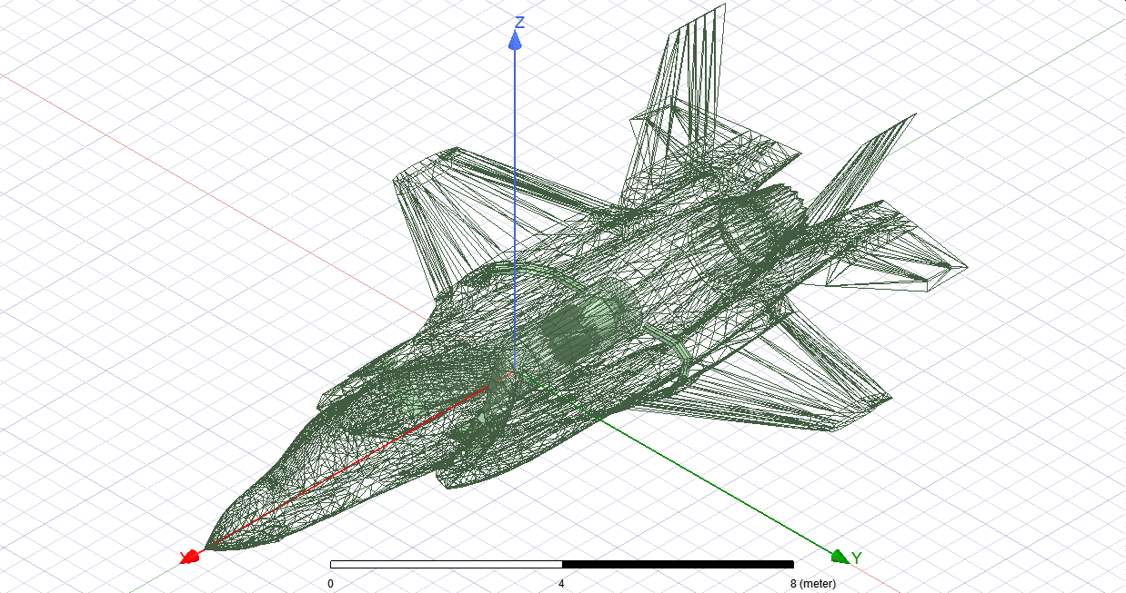

F-35A Radar scattering simulation
Introduction F-35 is the backbone of American stealth fighter fleet, it is intended to replace F-16, F-18C/D, Harrier and A-10. There are currently 3 versions of F-35 which are F-35A, F-35B and F-3…
basicsaboutaerodynamicsandavionics.wordpress.com
The aim of our simulation is to evaluate the mean and median radar cross section as well as the radar scattering pattern of the F-35A at 4 frequencies:
- VHF – 150 MHz
- L Band – 1150 MHz
- S Band – 3150 MHz
- X Band – 8150 MHz
- Case 1 is situation when the stealth aircraft have to face multiple radars located far from each others, thus they can illuminate the fighter from directions where the strong reflection lobes located
- Case 2 is situation when aircraft face small number of radars located close together so the stealth fighter can turn its nose toward targets
Basics Rules:
Similar to previous simulation. Because not every information about F-35 is available in the public sectors, we will follow several rules in the simulation.
- In real life, F-35 skin has a layer of radar absorbing material (RAM) to absorbing radar energy. However, in this simulation, all external surface including the canopy will be treated as perfect electrical conductor (meaning they will reflect radio wave like metal)
- Actual F-35 has trailing edge and leading edge treatment on its wings, horizontal and vertical stabilizers as well as inlet lips to reduce the magnitude of radar return from edge scattering and creeping wave return effect, however, those measure will not be added to our model.
- F-35 radome is a FSS radome, so it will be treated as perfect electrical conductor for all frequencies except the bandpass frequency
- For the configuration with AIM-9X as the wing tip weapon, the low observable SUU-96 pylon and LAU-151 rail will be used.
- Luneburg lens which often used to increase stealth aircraft's RCS will not be included in this simulation
- All cooling vents will be modeled
- The inlet and the first 2 fan stages of F-135 engine will be modeled (as radio wave with wavelength longer than X band can't reach the third fan stage).
- Even though there is no current data on the absorbing capability of the RAM used by F-35. The inner surface of the inlet duct leading to the engine stages will be coated with a layer of MnZn ferrite RAM. This rule is made due to the fact that it is not possible to evaluate the RCS reduction effect of radar blocker and/or S curve inlet without a layer of RAM added. The absorbing capability of the MnZn RAM will be based on actual real world measurement data. The current absorbing capability of the RAM used in our simulation is around -8 dB at 8.15 GHz and -4 dBsm at 3.15 GHz. Keep in mind though that actual RAM used on stealth aircraft may have absorbing rating of -15 to -25 dB depend on the actual frequency.
Model photos